4
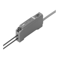
MOUNTING OF STANDARD TYPE SENSOR
䢇 A sensor mounting bracket MS-DPX and MS-DPX-4
(optional) may be used.
When mounting the sensor with the sensor mounting bracket,
etc., the tightening torque should be 1.2N·m or less.
䢇 Panel mounting bracket MS-DPX-2 (optional) and a front
protection cover DPX-04 (optional) are also available.
5
I/O CIRCUIT DIAGRAM
NPN output type
Tr2
Tr1
1kΩ
100mA max.
100mA max.
Users’ circuitInternal circuit
(Blue) 0V
(White) Comparative Output 2
(Black) Comparative Output 1
(Gray) Analog
voltage output
(Brown)
ⳭV
Color code
Load
Load
ZD2
ZD3
ZD1
D
12 to 24V DC
%
Ⳮ
ⳮ
Sensor circuit
Ⳮ10
ⳮ15
(Note)
Sensor mounting bracket
MS-DPX (optional)
M4 (length 6mm) pan head screw
(attached with MS-DPX)
Spring washer
(attached with MS-DPX)
D
P
2
-
2
0
–
1
0
1
.
3
k
P
a
O
U
T
2
O
U
T
1
M
O
D
E
0
-
A
D
J
Panel mounting bracket
MS-DPX-2 (optional)
(Suitable for 1 to 3.2mm thick panel)
D
P
2
-
2
0
–
1
0
1
.
3
k
P
a
O
U
T
2
O
U
T
1
M
O
D
E
0
-
A
D
J
Front protection cover
DPX-04 (optional)
Symbols
…
D: Reverse supply polarity protection diode
Z
D1, ZD2, ZD3: Surge absorption zener diode
Tr
1, Tr2: NPN output transistor
Note: The analog voltage output is not incorporated with a short-circuit
protection circuit. Do not directly connect a power supply or a
capacitive load. When using the analog voltage output, take
care to connect external equipment of proper input impedance.
Also, when a cable extension is used, voltage drop due to cable
resistance should be taken into account.
PNP output type
Users’ circuitInternal circuit
Color code
100mA max.
100mA max.
ZD1
ZD2
ZD3
Tr1
Load
Load
(Brown)ⳭV
(White) Comparative Output 2
(Black) Comparative Output 1
(Gray) Analog
voltage output (Note)
(Blue) 0V
12 to 24V DC
%
Ⳮ
ⳮ
Tr2
D
Sensor circuit
1kΩ
Ⳮ10
ⳮ15
Symbols
…
D: Reverse supply polarity protection diode
Z
D1, ZD2, ZD3: Surge absorption zener diode
Tr
1, Tr2: PNP output transistor
Note: The analog voltage output is not incorporated with a short-circuit
protection circuit. Do not directly connect a power supply or a
capacitive load. When using the analog voltage output, take
care to connect external equipment of proper input impedance.
Also, when a cable extension is used, voltage drop due to cable
resistance should be taken into account.
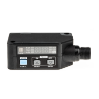
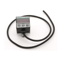
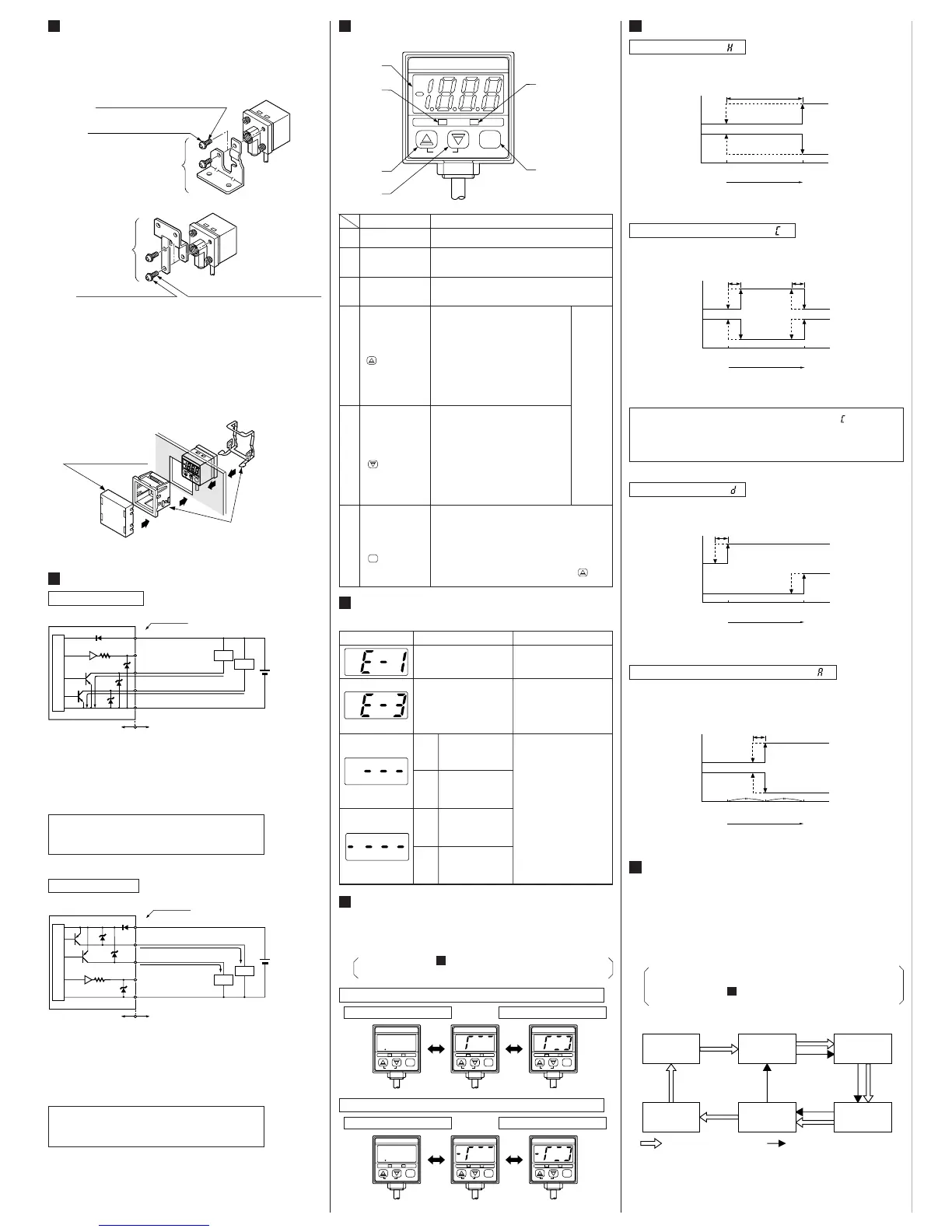
6
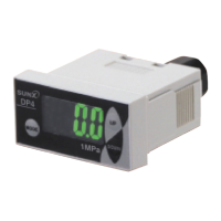
FUNCTIONAL DESCRIPTION OF
OPERATION PANEL
DP2-20
–101.3kPa
OUT2OUT1
MODE
0-ADJ
1
2
3
6
4
5
06H0129
Description Function
1
2
3
4
5
6
3
1
/
2
digit LED
display (Red)
Comparative Output 1
operation indicator
(Orange)
Comparative Output 2
operation indicator
(Green)
Increment key
()
Decrement key
()
Mode selection key
()
Displays measured pressure, settings, error mes-
sages and key-protect status.
Lights up when Comparative Output 1 is ON.
Lights up when Comparative Output 2 is ON.
• In the initial setting mode, pressing the
key changes the settable digit.
• In the Set Value 1, 2 modes, pressing
the key changes the set value to the
high pressure side in case of positive
pressure type sensor and to the high
vacuum side in case of vacuum pressure
type sensor.
•
In the sensing mode, if the key is pressed
continuously for 4 sec. or more, the display
shows peak hold value.
• In the initial setting mode, pressing the
key changes the set conditions.
• In the Set Value 1, 2 modes, pressing
the key changes the set value to the
low pressure side in case of positive
pressure type sensor and to the low
vacuum side in case of vacuum pressure
type sensor.
•
In the sensing mode, if the key is pressed
continuously for 4 sec. or more, the display
shows bottom hold value.
• Pressing the key changes the selected mode to
sensing mode, Set Value 1 (P1) set mode and Set
Value 2 (P2) set mode.
• In the sensing mode, if the key is pressed continu-
ously for about 3 sec., key-protect can be
set/released.
• In the sensing mode, if the mode selection key is
pressed while pressing the increment key ( ) , the
initial setting mode is obtained.
In the sensing mode, if both the keys are pressed
simultaneously, zero-point adjustment is done.
7
ERROR MESSAGES
䢇 When an error occurs, take the following corrective action.
Error message Cause Corrective action
Overcurrent due to short-
circuit.
Pressure is being applied
during zero-point adjust-
ment.
Positive
pressure
type
Vacuum
pressure
type
Positive
pressure
type
Vacuum
pressure
type
Applied pressure exceeds
the upper limit of dis-
playable pressure range.
Applied pressure exceeds
the lower limit of display-
able pressure range.
Applied pressure exceeds
the lower limit of display-
able pressure range.
Applied pressure exceeds
the upper limit of dis-
playable pressure range
.
Switch off the power supply
and check the load.
Applied pressure should be
brought within the rated
pressure range.
Applied pressure at the
pressure port should be
brought to atmospheric
pressure and zero-point
adjustment should be done
again.
8
ANALOG BAR DISPLAY
䢇
Pressure changes are displayed in an analog fashion by using LED bars.
Hence, any sudden changes in pressure can be detected at a glance.
䢇
The analog bar display shows the measured pressure, irrespective
of the pressure unit, in steps of 10% F.S. approx.
• Please refer to SETTING
2
Initial setting for the
procedure to change to analog bar display.
11
Analog bar display for positive pressure type sensor
Atm. pressure condition
Atm. pressure condition
High pressure condition
High vacuum condition
DP2-21
100kPa
OUT2OUT1
MODE
0-ADJ
DP2-21
100kPa
OUT2OUT1
MODE
0-ADJ
DP2-21
100kPa
OUT2OUT1
MODE
0-ADJ
06H0132
DP2-20
–101.3kPa
OUT2OUT1
MODE
0-ADJ
DP2-20
–101.3kPa
OUT2OUT1
MODE
0-ADJ
DP2-20
–101.3kPa
OUT2OUT1
MODE
0-ADJ
9
OUTPUT MODES & THEIR CHARACTERISTICS
Hysteresis mode ( )
䢇 The common hysteresis of the comparative outputs can be
set, as desired, with the set values.
Window comparator mode ( )
䢇
The comparative outputs can be turned ON or OFF by a pressure
which is within the pressure range set by Set Value 1 and Set Value 2.
Comparative
Output 1
Comparative
Output 2
ON
OFF
ON
OFF
0
Set Value 1 (P1) Set Value 2 (P2)
High pressure
(Positive pressure type)
High vacuum
(Vacuum pressure type)
Hysteresis
()
Hysteresis: 1 digit or more
2 digits or more when
using psi unit
Comparative
Output 1
Comparative
Output 2
ON
OFF
ON
OFF
0
Set Value 1 (P1)
Set Value 2 (P2)
High pressure
(Positive pressure type)
High vacuum
(Vacuum pressure type)
Hysteresis Hysteresis
Hysteresis: 1 digit
2 digits when
using psi unit
()
Comparative
Output 1
Comparative
Output 2
ON
OFF
ON
OFF
0
Set Value 1 (P1) Set Value 2 (P2)
High pressure
(Positive pressure type)
High vacuum
(Vacuum pressure type)
Hysteresis: 1 digit
2 digits when
using psi unit
Hysteresis
()
Dual output mode ( )
䢇 The outputs can be put to different use such as detection of
different kinds of objects, control function, alarm function etc.
Comparative
Output 1
Comparative
Output 2
ON
OFF
ON
OFF
0
Set Value 1 (P1) Set Value 2 (P2)
Set Value 3 (P3)
High pressure
(Positive pressure type)
High vacuum
(Vacuum pressure type)
Hysteresis
Hysteresis: 1 digit
2 digits when
using psi unit
()
Automatic sensitivity setting mode ( )
䢇 Using actual objects, if the pressure values for OK objects
and NG objects are input, then the sensor is automatically set
to the optimum pressure value (mid-value).
10
PRESSURE UNITS
䢇 The pressure unit can be selected as per customer’s
requirement.
䢇 In case of positive pressure type, the pressure unit can be
changed from International System of Units (SI) ‘kPa’ or
‘MPa’ to ‘kgf/cm
2
’, ‘bar’ or ‘psi’. In case of vacuum pressure
type, the pressure unit can be changed from International
System of Units (SI) ‘kPa’ to ‘kgf/cm
2
’, ‘bar’, ‘psi’, ‘mmHg’ or
‘inHg’.
•
When the pressure unit is changed, the set values and the
measured value are automatically converted.
• Please refer to SETTING
2
Initial setting for the
procedure to change the pressure unit.
11
inHg
kPa (Note)
kgf/cm
2
mmHg psi bar
: Positive pressure type: Vacuum pressure type
International System
of Units (SI)
• When operating in window comparator mode ( ) Set Value
1 (P1) and Set Value 2 (P2) should be set with a difference
of 3 digits or more. However, when the pressure unit is set
to ‘psi’, the difference should be 6 digits or more.
Note: MPa in case of DP2-22䡺, DP2-42䡺 and DP2-62䡺.
Analog bar display for vacuum pressure type sensor
Sensor mounting
bracket
MS-DPX-4 (optional)
M4 (length 6mm) pan head screw
(attached with MS-DPX-4)
Spring washer
(attached with MS-DPX-4)
Note: In case mounting brackets or screws other than the sensor
mounting bracket shown in the fiqure above are used, the length
of the screws inserted into the pressure port attachment should
be 5mm or less. If the length of the screws is longer than 5mm,
the sensor may be damaged.
<MS-DPX-4>
<
MS-DPX>
 Loading...