Note: Take care that if the connector is pulled out without
pressing the release lever, cable or connector may
break.
Disconnection method
Pressing the release lever of the cable with con
-
nector, pull out the connector.
Ɣ
<Connector pin arrangement>
Connector pin No. Terminal name
1+V
2 Output
3 External input
40V
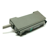
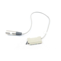
Insert the cable with connector &1$&Ƒinto
this product's connector area as shown in the
right figure.
Ɣ
WIRING
3
Connection method
Cable with
connector
CN-14A-CƑ
RUN MODE
5
7KUHVKROGYDOXH¿QHDGMXVWPHQWIXQFWLRQ
Fine adjustment of threshold value can be done when in RUN mode.
Press the set value UP key or set value DOWN key to change threshold
value. (Hold down the key to make the value change faster.)
The threshold value is stored after 3 sec.
Ɣ
Ɣ
Ɣ
<When in RUN mode>
Incident light
intensity
Threshold
value
<When turning ON the power>
Emission
frequency
Product
name
<RUN mode>
Incident light
intensity
Threshold
value
Automatic
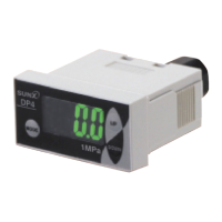
When turning ON the power, the product name is indicated on the green
digital display, while the emission frequency is indicated on the red digital
display. Then switches into RUN mode [digital display (green: threshold
value, red: incident light intensity)].
Ɣ
<Digital display>
When selecting emission halt in the external input setting mode and re-
ceiving the signal externally, “ ” is indicated on the red digital display.
When selecting ECO in the external input setting mode, key operation on
the main body is invalid during external input.
When selecting 2-point teaching in the external input setting mode, “ ”
is indicated on the green digital display after inputting the first point.
When ECO setting mode is ON, the digital display turns off in approx. 20
sec. In case of lighting up the digital display again, press any key for 2
sec. or more.
For the settings of external input and ECO, refer to “ PRO MODE.”
Ɣ
Ɣ
Ɣ
Ɣ
Ɣ
Thank you very much for using SUNX products. Please read this Instruc
-
tion Manual carefully and thoroughly for the correct and optimum use of this
product. Kindly keep this manual in a convenient place for quick reference.
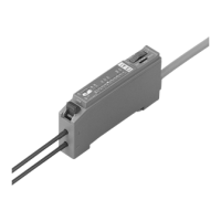
FX-100 Series
INSTRUCTION MANUAL
Digital Fiber Sensor
Photoelectric Sensor
MJE-FX100 No.0009-43V
WARNING
Never use this product as a sensing device for personnel protection.
In case of using sensing devices for personnel protection, use products
which meet laws and standards, such as OSHA, ANSI or IEC etc., for
personnel protection applicable in each region or country.
Ɣ
Ɣ
+RZWRFRQQHFWWKH¿EHUFDEOH
%HVXUHWR¿WWKHDWWDFKPHQWWRWKH¿EHUV¿UVWEHIRUHLQVHUWLQJWKH¿EHUVWRWKH
DPSOL¿HU)RUGHWDLOVUHIHUWRWKH,QVWUXFWLRQ0DQXDOHQFORVHGZLWKWKH¿EHUV
1. Snap the fiber lock lever down, till it stops
completely.
2. Insert the fiber cables slowly into the inlets
until they stop. (Note 1)
5HWXUQWKH¿EHUORFNOHYHUWRWKHRULJLQDOSRVL
-
tion, till it stops.
1
3
2
Fiber lock
lever
Fiber
MOUNTING
2
+RZWRPRXQWWKHDPSOL¿HU
1. Fit the rear part of the mounting section of the
DPSOL¿HURQDPPZLGWK',1UDLO
2. Press down the rear part of the mounting
VHFWLRQRIWKHXQLWRQWKHPPZLGWK',1UDLO
DQG¿WWKHIURQWSDUWRIWKHPRXQWLQJVHFWLRQ
to the DIN rail.
1
2
35mm width DIN rail
<When using a DIN rail>
+RZWRUHPRYHWKHDPSOL¿HU
3XVKWKHDPSOL¿HUIRUZDUG
/LIWXSWKHIURQWSDUWRIWKHDPSOL¿HUWRUHPRYH
it.
1
2
<When using screws with washers>
Use M3 screws with washers for mounting.
7KHWLJKWHQLQJWRUTXHVKRXOGEH1ÂPRU
less.
Ɣ
M3 screw
with washer
1RWH 7DNHFDUHWKDWLIWKHIURQWSDUWLVOLIWHGZLWKRXWSXVKLQJWKHDPSOL¿HUIRUZDUGWKH
hook on the rear portion of the mounting section is likely to break.
1RWHV,QFDVHWKH¿EHUFDEOHVDUHQRWLQVHUWHGWRDSRVLWLRQZKHUHWKH\VWRSWKH
VHQVLQJUDQJHUHGXFHV6LQFHDÀH[LEOH¿EHULVHDVLO\EHQWWDNHFDUHZKHQ
it is inserted.
:LWKWKHFRD[LDOUHÀHFWLYHW\SH¿EHUVXFKDV
FD-G4 or FD-FM2, insert the
VLQJOHFRUH¿EHUFDEOH LQWRWKHEHDPHPLWWLQJLQOHW ³3´DQGWKHPXOWLFRUH
¿EHUFDEOHLQWRWKHEHDPUHFHLYLQJLQOHW³'´,IWKH\DUHLQVHUWHGLQUHYHUVH
the sensing performance will deteriorate.
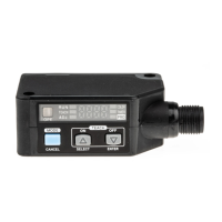
PART DESCRIPTION
1
MODE key
ON key /
Set value UP key
Operation indicator
(Orange)
OFF key /
Set value DOWN key
Digital display (Green)
(Threshold value)
Digital display (Red)
(Incident light intensity)
<Operating portion>
MODE key
ON key /
Set value UP key
OFF key /
Set value DOWN key
Â6HOHFWLRQRIVHWWLQJLWHPV
Â&RQ¿UPDWLRQRIVHWFRQWHQWV
Â6HOHFWLRQRIVHWWLQJFRQWHQWV
Â6HWWLQJVLQWHDFKLQJPRGH
Note : Press MODE key for 2 sec. or more while setting other than RUN mode, to re
-
turn to RUN mode.
I/O CIRCUIT DIAGRAMS
4
<NPN output type>
+
–
8V
*1
Main circuit
Internal circuit Users’ circuit
100mA max.
(Brown) +V
(Black) Output
(Blue) 0V
(White) External input
Color code of cable with connector
12 to 24V DC
±10%
Load
Connector pin No.
<PNP output type>
*2
Main circuit
Internal circuit Users’ circuit
100mA max.
(Brown) +V
(Black) Output
(Blue) 0V
(White) External input
Color code of cable with connector
+
–
12 to 24V DC
±10%
Load
Connector pin No.
*1
Non-voltage contact or NPN open-collector transistor
or
High (+8V to +V DC or Open): Invalid
/RZ>WR9'&6RXUFHFXUUHQWP$RUOHVV@9DOLG
*2
Non-voltage contact or PNP open-collector transistor
+LJK>9WR9'&6LQNFXUUHQWWRP$RUOHVV@9DOLG
Low (0 to +0.6V DC or Open): Invalid
'LJLWDO¿EHUVHQVRUFX-100 VHULHVKDVEHHQPRGL¿HGVLQFH
production in December, 2007. Hence, this instruction
PDQXDOKDVEHHQFKDQJHGWRUHÀHFWWKHPRGL¿FDWLRQV