٨ Full auto-teaching is used when it is desired to set the threshold value without
stopping the assembly line, with the object in the moving condition.
In case of full auto-teaching
Set the mode selection switch to 'RUN'.
The threshold value does not change even if the jog switch is operated.
If teaching is accepted, the read incident light intensity is displayed for 0.5 sec. approx., and the threshold
value is set to the middle value of the incident light intensity levels in the object present and object absent
conditions. After that, the judgement on the stability of sensing is displayed for 2.5 sec. approx.
After this, the threshold value is displayed.
In case stable sensing is possible: ' ' is displayed.
In case stable sensing is not possible: ' ' is displayed.
or
Set the mode selection switch to 'SET'.
The present threshold value is displayed.
Set to either Output 1 or Output 2 by turning the jog switch to the '+' or the '
-
'
side.
1
2
Output 1
1
2
Output 2
LCD display
Description
Step
Set the fiber within the sensing range.
Set the mode selection switch to either 'RUN' or 'MODE'.
Ԝ
Press the jog switch continuously for 3 sec. or more with the object moving on
the assembly line.
ԛ
Ԛ
Ԙ
ԙ
ԝ
ԟ
Ԟ
' ' is displayed on the LCD display. Release the jog switch when the object has
passed.
<Procedure for maximum sensitivity setting>
Ԙ
ԙ
Ԛ
ԛ
Ԝ
ԝ
Ԟ
Set the mode selection switch to either 'RUN' or 'MODE'.
Set to either Output 1 or Output 2 by turning the jog switch to the '+' or the '
-
' side.
Set the mode selection switch to 'SET'.
Press the jog switch in the condition when there is no object or background body.
If teaching is accepted, ' ' is displayed on the LCD display.
Once again, press the jog switch in the condition when there is no object or background body.
Set the mode selection switch to 'RUN'.
Note:
Please take care that, if the sensor is set to max. sensitivity, it becomes weak against extraneous light,
noise and optical interference.
In case of fine adjustment
Set the mode selection switch to 'RUN'.
The threshold value does not change even if the jog switch is operated.
Set the mode selection switch to 'SET'.
The present threshold value is displayed.
1
2
Output 1
1
2
Output 2
Set to either Output 1 or Output 2 by turning the jog switch to the '+' or the '
-
'
side.
Set the mode selection switch to either 'RUN' or 'MODE'.
LCD display
Description
Step
Ԙ
Ԝ
Ԛ
ԙ
ԛ
In case the threshold value is to be increased (sensitivity to be reduced), turn the
jog switch a little to the '+' side to increase the threshold value slowly. If the jog
switch is turned fully to the '+' side, the threshold value increases rapidly.
In case the threshold value is to be decreased (sensitivity to be increased), turn
the jog switch a little to the '
-
' side to decrease the threshold value slowly. If the
jog switch is turned fully to the '
-
' side, the threshold value decreases rapidly.
or
SETTING OF EACH MODE
10
In case only a part of the settings are to be changed, set the mode selection switch
to 'RUN', at the appropriate time, in the middle of the above procedure to make only
the required changes.
Press the jog switch at the output operation desired to be set.
Ԛ
Turn the jog switch to either the '+' or the '
-
' side. The bar display
alternates between Output 1 and Output 2.
(The bar display on the extreme left blinks.)
Press the jog switch at the output desired to be set.
LCD display
Description
Step
Output
setting
Output operation
setting
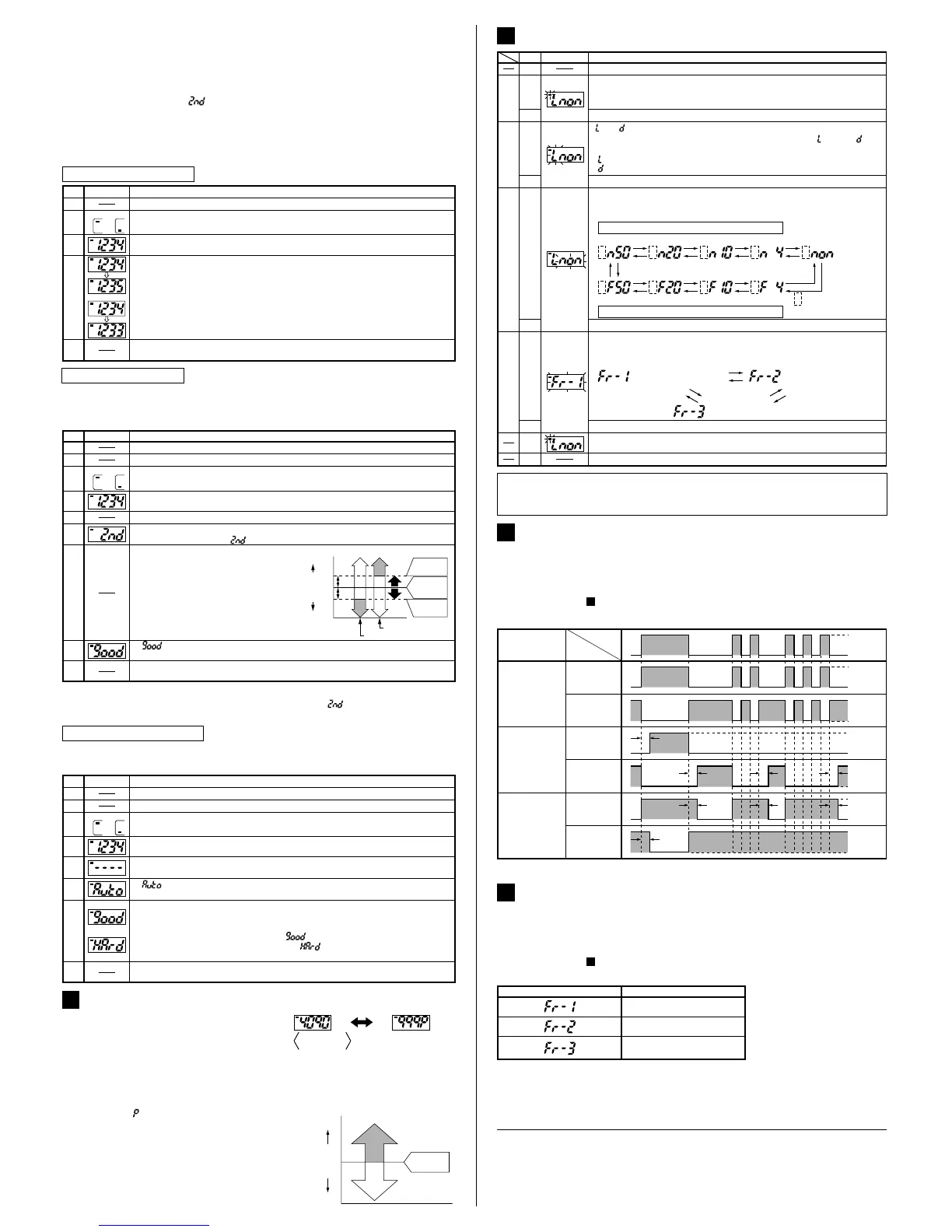
Timer operation setting
Emission frequency
setting
Ԙ
Set the mode selection switch to 'MODE'.
ԙ
Ԝ
ԛ
: Light-ON
: Dark-ON
(' ' or ' ' blinks.)
Turn the jog switch to either the '+' or the '
-
' side. ' ' and ' ' are
displayed alternately.
Press the jog switch at the timer operation desired to be set.
Ԟ
ԝ
Turn the jog switch to either the '+' or the '
-
' side. The display of timer
operation changes as given below.
(3 digits from the right side blink.)
ON-delay timer
OFF-delay timer
500ms 200ms 100ms 40ms
(Without timer)
+
-
+
-
+
-
+
-
500ms 200ms 100ms 40ms
The output operation set
at the 'output operation
setting' is displayed.
:
+
-
+
-
+
-
+
--
+
Press the jog switch at the emission frequency desired to be set.
Ԡ
ԟ
After the modification of settings, the display returns to the initial display.
ԡ
Set the mode selection switch to 'RUN' after finishing the settings.
Ԣ
Turn the jog switch to either the '+' or the '
-
' side. The display of emission
frequency changes as given below.
(The display changes and all digits blink.)
(Emission frequency 1) (Emission frequency 2)
(Emission frequency 3)
+
-
+
-
+
-
٨ FX-D1 series incorporate an ON-delay timer, which is useful when sensing only
objects with a long passage time, and an OFF-delay timer, which is useful when
the sensor is connected to devices having a slow response time. The timer period
can be selected from four values: 40ms, 100ms, 200ms and 500ms.
Please refer to ' SETTING OF EACH MODE' for the setting method.
10
TIMER FUNCTION
11
Timer period: T=40ms, 100ms, 200ms, 500ms (selectable at the time of 'MODE' setting)
<Time chart>
Timer operation
Normal
Light-ON
Dark-ON
Dark-ON
Dark-ON
Light-ON
Light-ON
Output
operation
Sensing
condition
ON-delay timer
OFF-delay timer
T
T
T
TTT
TT
ON
OFF
ON
OFF
ON
OFF
ON
OFF
ON
OFF
ON
OFF
Light
Dark
٨ Since the FX-D1 series incorporate an interference prevention function, up to 3
sets of fibers can be mounted close to each other by setting different emission
frequencies. Further, close mounting is also possible along with fibers which are
fitted to the fiber sensor amplifiers, FX-A1 series and FX-M1 series.
Please refer to ' SETTING OF EACH MODE' for the setting method.
However, note that the response time varies with the emission frequency as given below.
10
INTERFERENCE PREVENTION FUNCTION
12
Emission frequency
0.5ms or less
0.65ms or less
0.75ms or less
Response time
Note: Do not set the threshold value when interfering light is incident.
Correct incident light intensity cannot be taught in this condition.
Description
٨ This is the method of setting the threshold value by teaching only the object absent
condition (incident light stable condition). This is used for detection in presence of a
background body or for detection of small objects.
If the jog switch is pressed continuously for 3 sec., or more, full auto-teaching is done.
If the mode selection switch is changed to 'RUN' when '˴˴' is being displayed on the
LCD display, the incident light intensity taught at Step Ԝ is not recorded.
Notes: 1)
2)
In case of limit teaching
Set the mode selection switch to 'SET'.
The present threshold value is displayed.
1
2
Output 1
1
2
Output 2
Set the mode selection switch to either 'RUN' or 'MODE'.
Set the mode selection switch to 'RUN'.
The threshold value does not change even if the jog switch is operated.
If teaching is accepted, the read incident light intensity is displayed for 0.5 sec.
approx. Subsequently, ' ' is displayed on the LCD display. (Note 2)
Press the jog switch in the object present condition and release it within 3 sec. (Note 1)
Set to either Output 1 or Output 2 by turning the jog switch to the '+' or the '
-
'
side.
Set the fiber within the sensing range.
Ԡ
ԟ
' ' is displayed on the LCD display.
After that, the threshold value is shown.
ԝ
Ԟ
Ԝ
ԛ
Ԛ
LCD display
Step
Ԙ
ԙ
'+' side:
'
-
' side:
The threshold value is shifted to a
value approx. 15% lower (higher
sensitivity) than that set at Ԝ. Used
in case of thru-beam type fiber.
The threshold value is shifted to a
value approx. 15% higher (lower
sensitivity) than that set at Ԝ. Used
in case of reflective type fiber.
Turn the jog switch to either the '+' or the '
-
' side.
15%
15%
100%
0
OFF
ON
Turn to '+' side
Turn to '
-
' side
Threshold
value
Threshold
value
Incident light
intensity with
object absent
OFF
ON
High
Threshold
value
Low
PERCENTAGE DISPLAY
9
٨
After setting the threshold value, the current incident
light intensity can be expressed as a percentage of the
threshold value so that the degree of margin can be
confirmed at a glance. If the jog switch is pressed when
the mode selection switch is set on 'RUN', the display
changes from absolute value to percentage value, and
0 to 999% is displayed. However, % (percent) is
expressed by ' ' and fractions are rounded off.
If the jog switch is pressed once again, the
display returns to absolute value.
Further, in case percentage display is desired
when the power supply is switched off, and then,
on again, change the mode selection switch once
to 'SET' or 'MODE', and then, set it back to 'RUN'.
Threshold
value
100%
Large
Light-ON
Dark-ON
Small
Incident light intensity
(percentage display)
The larger the difference between the
numerical values in the Light state and the
Dark state, more stable is the sensing.
Percentage display=
Current incident light intensity
¸Threshold value100(%)
<Percentage display>
Current incident
light intensity
PRINTED IN JAPAN
Head Office
2431-1 Ushiyama-cho, Kasugai-shi, Aichi, 486-0901, Japan
Phone: +81-(0)568-33-7211 FAX: +81-(0)568-33-2631
Overseas Sales Dept.
Phone: +81-(0)568-33-7861 FAX: +81-(0)568-33-8591
http://www.sunx.co.jp/
SUNX Limited
 Loading...