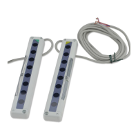
Job indicator (Red)
Emitting indicator (Green)
Operation mode switch
Job indicator (Red)
Stable incident beam indicator (Green)
Operation indicator (Red)
Operation mode switch
1
2
3
4
O
N
No.
4
3
1
2
Description OFF side
Emission frequency selection
Job indicator operation selection
Job indicator operation selection
Operation indicator / test input selection
ON side
Job indicator input Test input
Lights up Blinks
Frequency A Frequency B
ReceiverEmitter
Lights up when job
indicator input is Low
Lights off when job
indicator input is Low
The operation of the job indicator can be selected with the job indicator
mode switch.
Job indicator input signal condition
Operation mode
switch
Job indicator input: Low Job indicator input: High
Job indicator operation
1
2
3
4
1
2
3
4
1
2
3
4
1
2
3
4
Lights offLights up
Lights upLights off
BlinksLights up
BlinksLights off
Signal
Low
High
Low
High
Signal condition
0 to 2V
5 to 30V, or open (Note)
0 to 2V, or open (Note)
8V to +V
Output
NPN output
PNP output
Note: Insulate the wire if it is kept open.
The job indicators can be used as large operation indicators by setting
No. 4 of the operation mode switch to the OFF side and connecting the
input (pink) of the emitter to the output (black) of the receiver.
Job indicator
mode switch
Light state Dark state
1
2
3
4
1
2
3
4
1
2
3
4
1
2
3
4
Note:
In order to use the job indicators as large operation indicators, make sure to set
No. 4 of the operation mode switch to the OFF side. If it is set to the ON side, the
job indicator does not light up or blink.
Lights up Light off
Lights up
Blinks
Blinks
Light off
Lights up
Light off
The emission is stopped when No. 4 of the operation mode switch is set
to the ON side and the input (pink) of the emitter is made High (PNP
output type: Low).
Since the output can be turned ON/OFF without the sensing object, this
function is useful for start-up inspection. If the output follows the
application/withdrawal of the test input, the sensor operation is normal,
else it is abnormal.
OFF
1
2
3
4
Notes: 1)
2)
When the test-run function is set, the job indicator (red) does not light up or blink.
When emission is stopped during the test-run function, the emitter
,
s emitting
indicator (green) does not light up.
Operation mode switch setting
Time chart
ON
High
Test input
Output
Low
ON
T
1 35ms, T2 = 35ms
When using interference
prevention function
T
1 42ms, T2 = 42ms
T
1
T2
OFF
1
2
3
4
T2
(In case of Light-ON)
By setting different emission
frequencies, two units of NA2-N can
be mounted close together, as shown
in the figure on the right. The emission
frequency can be checked by the
number of LEDs lighting up in the
emitting indicator on the emitter.
Emitting indicator (Emitter)Operation mode switch
Sensor
B
Sensor
A
Sensor
Frequency A
One LED lights up
Frequency B
1
2
3
4
1
2
3
4
A
Sensor
B
Two LEDs light up
Place the emitter and the receiver face
to face along a straight line.
After the cables have been correctly
connected, switch the power ON.
Move the emitter in the up, down, left
and right directions, in order to determine
the range of the beam received condition
with the help of the operation indicator
on the receiver. Then, set the emitter at
the center of this range.
Similarly, adjust for up, down, left and
right angular movement of the emitter.
Further, perform the angular adjustment for the receiver also.
Check that the stable incident beam indicator (green) lights up.
Interrupt each beam channel with the actual sensing object, and confirm
that the sensor operates correctly.
Note:
The stable incident beam indicator (green) lights up when all the light beams are
stably received.
Operation
indicator
Stable incident
beam indicator
Receiver
Emitter
PRINTED IN JAPAN
Head Office
Phone: +81-
(
0
)
568-33-7861 FAX: +81-
(
0
)
568-33-8591
2431-1 Ushiyama-cho, Kasugai-shi, Aichi, 486-0901, Japan
Phone: +81-
(
0
)
568-33-7211 FAX: +81-
(
0
)
568-33-2631
Overseas Sales Dept.
http://www.sunx.co.jp/ SUNX Limited
 Loading...