11
3 - Electrical Connections
PRECAUTIONS
B
The instrument has been
designed to work in an harsh
and noisy environmental (level IV
of the industrial standard IEC
801-4). It is recommended to
follow the following suggestions.
A
All the wiring must comply
with the local regulations.
The supply wiring should be
routed away from the power
cables. Avoid to place electro-
magnetic contactors, power
relays and high power motors
nearby. Avoid power units in
close proximity, especially if
controlled in phase angle mode.
Keep the low level sensor
input wires away from the
power lines and the output
wiring. If this is not achiev-
able, use shielded cables on
the sensor input, with the
shield connected to ground.
Conduit for supply and output cables
Conduit for low level sensor cables
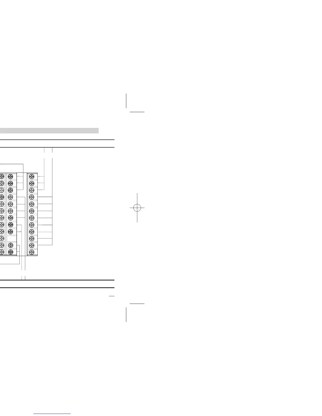
3.2 SUGGESTED WIRES ROUTING
B
A = Supply
B = Outputs
C = Analog inputs
D = Analog output
E = Digital input
Serial Comm.s