12
3 - Electrical Connections
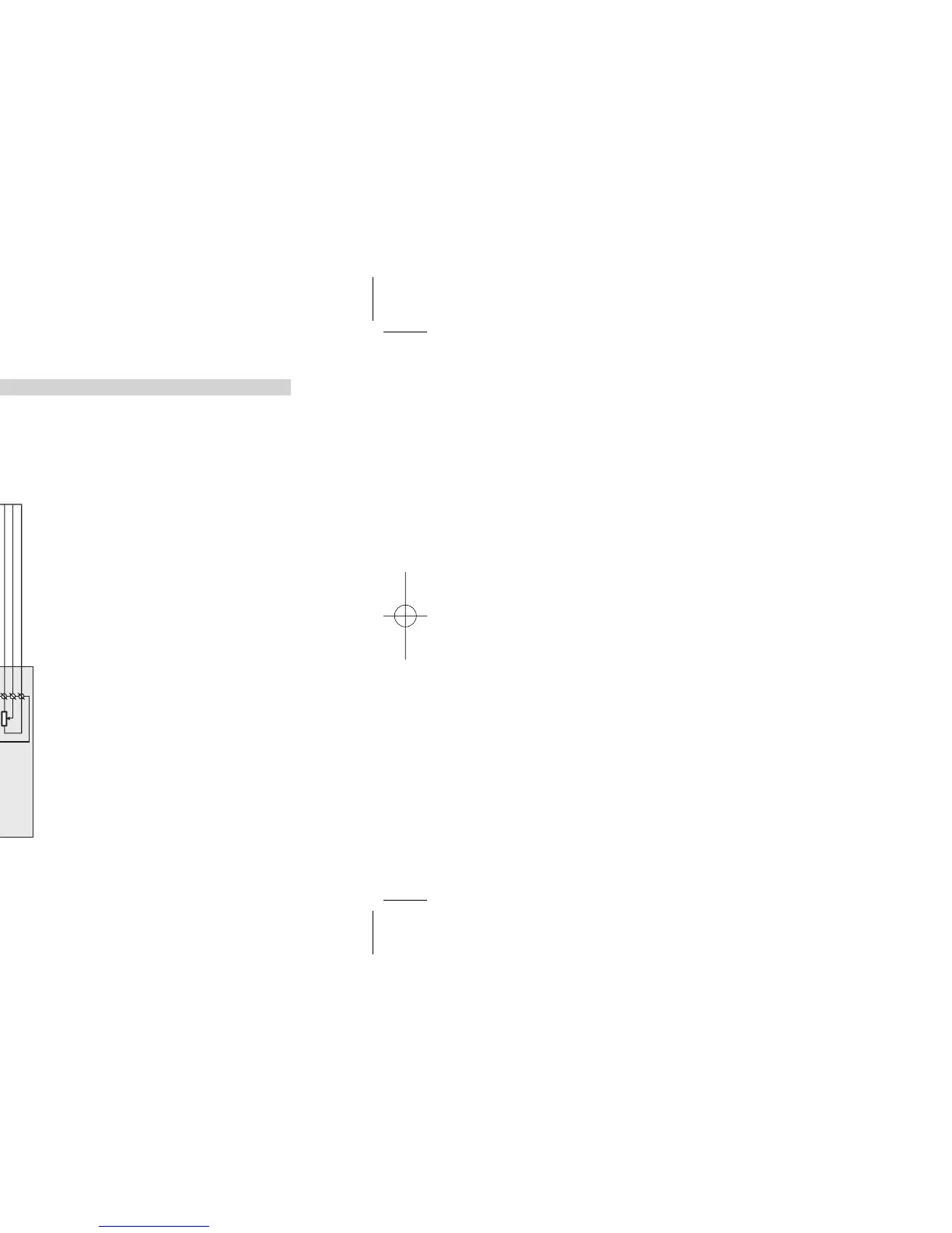
3.3 EXAMPLE OF WIRING DIAGRAM (VALVE CONTROL)
B
Notes:
1] Ensure that the power supply voltage is
the same as that on the instrument label.
2] Switch ON the power supply only after
all electrical connections have been
completed.
3] In accordance with electrical safety reg-
ulations, there must be an easly identifi-
able and accessable power disconnect.
4] The instrument is PTC protected.
In case of failure, return the instrument to
the manufacturer for repair.
5] To protect internal circuits use:
- 2 A
~ T fuse for Relay outputs (220 Vac)
- 4 A~ T fuse for Relay outputs (110 Vac)
- 1 A~ T fuse for Triac outputs
6] Relay contacts are protected with varis-
tors.
In case of 24 Vac inductive loads, use
model A51-065-30D7 varistors (on
request).