16
3 - Electrical Connections
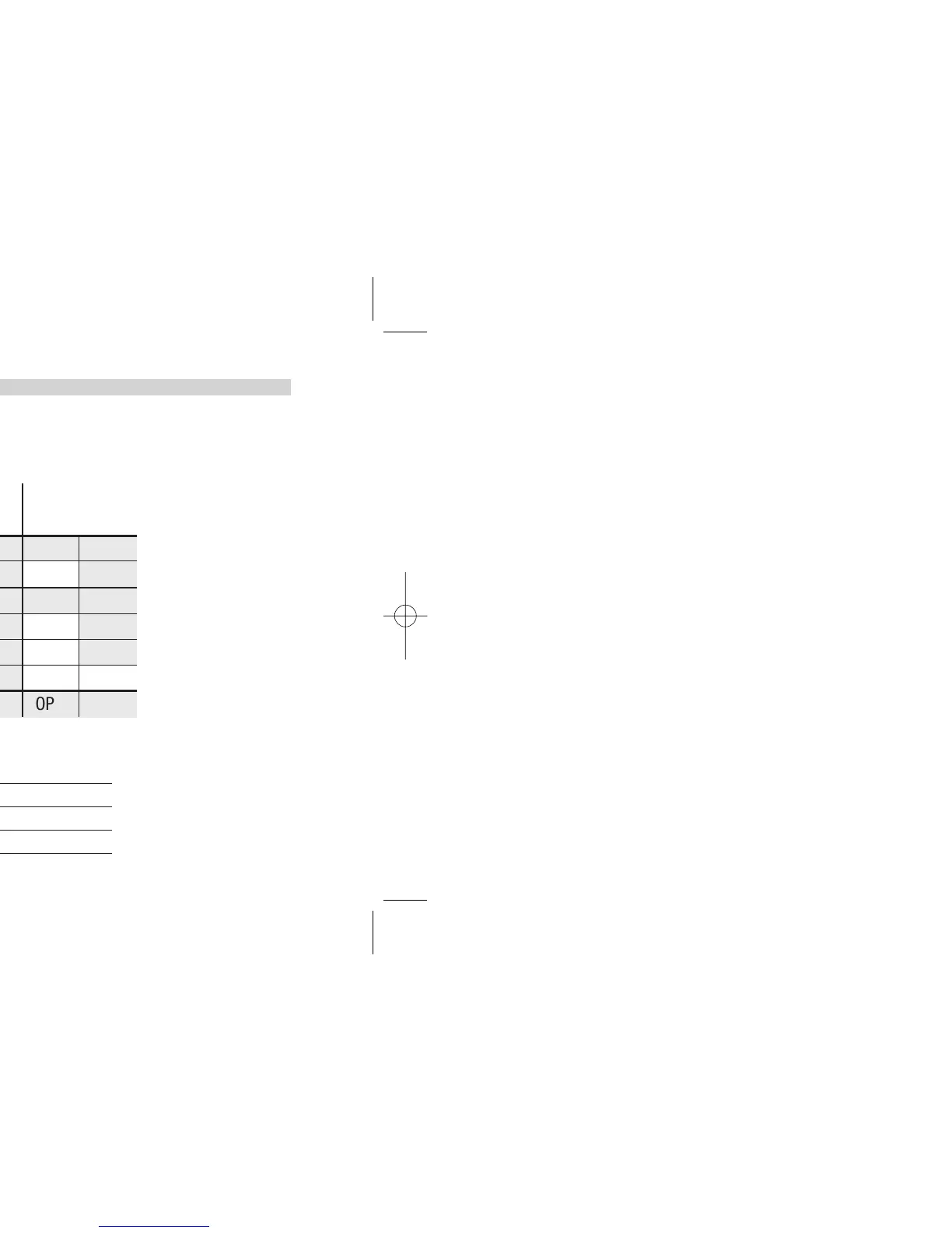
3.3.6 OP1 - OP2 - OP3 - OP4 - OP5 - OP6 OUTPUTS (OPTION)
B
The functionality associated to each of OP1, OP2, OP4, OP5 and OP6 is defined during the configuration of the instrument.
The allowed combinations are:
Control outputs Alarms Retransmission
Main (Heat) Secondary (Cool) AL1 AL2 AL3 PV / SP / MV
A
OP1
OP2 OP3 OP5
B
OP5
OP1 OP2 OP3
D
OP1 OP2
OP3 OP5
E
OP1 OP5
OP2 OP3
F
OP5 OP2
OP1 OP3
G
OP5 OP6
OP2 OP3
OP1 - OP2
Relay or Triac output
OP3 - OP4
Relay outputs
OP5 - OP6
Analog control or retransmission outputs
where:
L
OP1
s
OP2
t
OP3 OP5OP4
OP4
OP4
OP4
OP4
OP4
OP4
AL4
OP6
Single
action
Double
action
Valve drive
OP6
OP6
OP6
OP6
OP6