•
Galvanic isolation 500 Vac/1 min
• Compliance to the EIA RS485
standard for PROFIBUS DP;
• Connecting cable: twisted
pair cable as per PROFIBUS
specifications (e.g. Belden
B3079A);
• Max. lenght: 100 m at 12 Mb/s
Termination resistors 220Ω and
390Ω (
1
/
4
W, ±5%) for external
mounting on the first and end-
ing PROFIBUS stations only.
Detailed information concerning wiring and cables can be found on
the PROFIBUS Product Guide on Internet at:
http://www.profibus.com/online/list
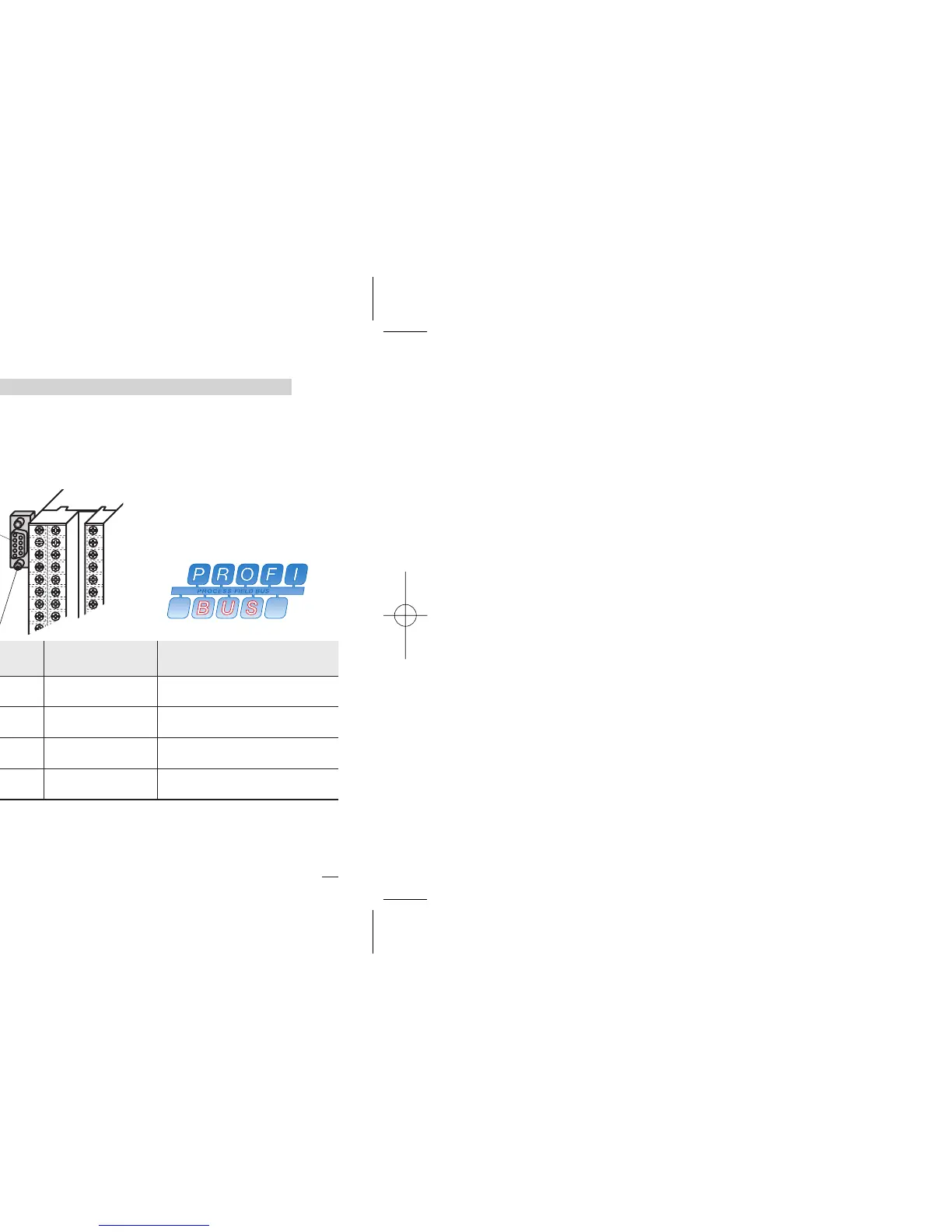
To make the connections easier, a D-Sub type (9 poles)
connector, model AP-ADP-PRESA-DSUB/9P is provided
Must be used with a 9PIN male ERNI type part no. 103648 or sim-
ilar connector.
X5 D-SUB 9 poles Signal
Description according to
PROFIBUS specifications
4
1 3 RxD/TxD-P (DP)
Receive data/transmission
data plus
6
2 8 RxD/TxD-N (DN)
Receive data/transmission
data negative
VP (VP)
3 5 DGND (DG)
Data transmission potential
(ground to 5V)
Supply voltage of the termi-
nating resistance-P, (P5V)