~
GENERALINFORMATION
Thisappliance compUeswithNational Safely Stan-
dards and is tested and listed by Underwriters
Laboratories, Inc. to ANSI Z21.50-1986 as a vented
decorative gas appliance.
Installation must conform to local codes. In the
absence of local codes installation must conform
with the current National Fuel Gas Code, ANSI
Z223.1. Theappliance,when installed,must be
electricallygroundedinaccordance withlocalcodes,
withthe National ElectricalCode, ANSIINFPANo.
70-1984.
Note: Installationandrepairshouldbedonebya
qualifiedserviceperson.Theapplianceshouldbe
inspectedannually
byaprofessionalserviceper-
son.Morefrequentinspectionslc/eaningsmaybe
requireddw toexcessive/intfromcarpeting,bed-
dingmaterial,etc.Itis imperativethatthecontrol
compartment,burnersandcirculatingairpassage
waysoftheappliancebekeptclean.
Provide for adequate ventilation.
~
Provide adequate clearances around air openings
and adequate accessibility dearance for service
and proper operation. Never obstruct the front
opening ofthe fireplace.
Minimumclearances to combustibles are:
Sides 112', Floor 0', Back 112', Ceiling 41 112',
Sidewall O', Vent Surfaces 1'.
Minimum inlet gas pressure is 4.5 inches water
column for natural gas and 11 inches water column
propane for the purpose of input adjustment.
Maximuminlet gas supply pressure is 7.0 inches
water column fornatural gas and 13.0 inches water
column forpropane.
Input is 18,000 aTUMR
A 1/8' N.P.T. plugged tapping is provided on the
gas control along side of the outlet to the main
burner for a test gage connection.
This apptiance must oot be connected to a chimney
flue servicing a solid fuel burning appliance.
The appliance must be isolated from the gas supply
piping system by dosing its individual manual shut-
off valve during any pressure testing of the gas
supply piping system altest pressures equal to or
more than 112 psig.
2
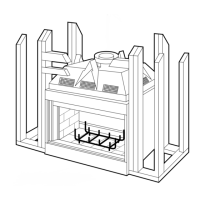
INTRODUCTION
The GHC-SOOOis a heat circulating system that
utilizing a miUivok gas control valve and a piezo
ignition system. Glass doors, trim kits and a forced
air fan assembly are optional equipment.
The GRD-SOOO
is a radiant heat system that utiliz-
ing a millivoh gas control valve and a piezo ignition
system. Glass doors are optional equ~ment.
ASSEMBLYSTEPS
1.Position appliance prior to framing or into pre-
pared framing.
2.Route gas line to firebox compartment and install
m~livoh waD switch.
3. Install vent system.
4. Field wire main power supply to appliance junc-
tion box (only if optional fan assembly is to be
installed aI a later time).
5. Complete finished wall malerial and trim.
6. Install controls and burner assembly. Connect to
gas supply.
7. Wife remote millivolt wall switch to control valve.
8. Attach horizontal louvers andlor optional \rim
pieces.
9. Install the optional glass doors.
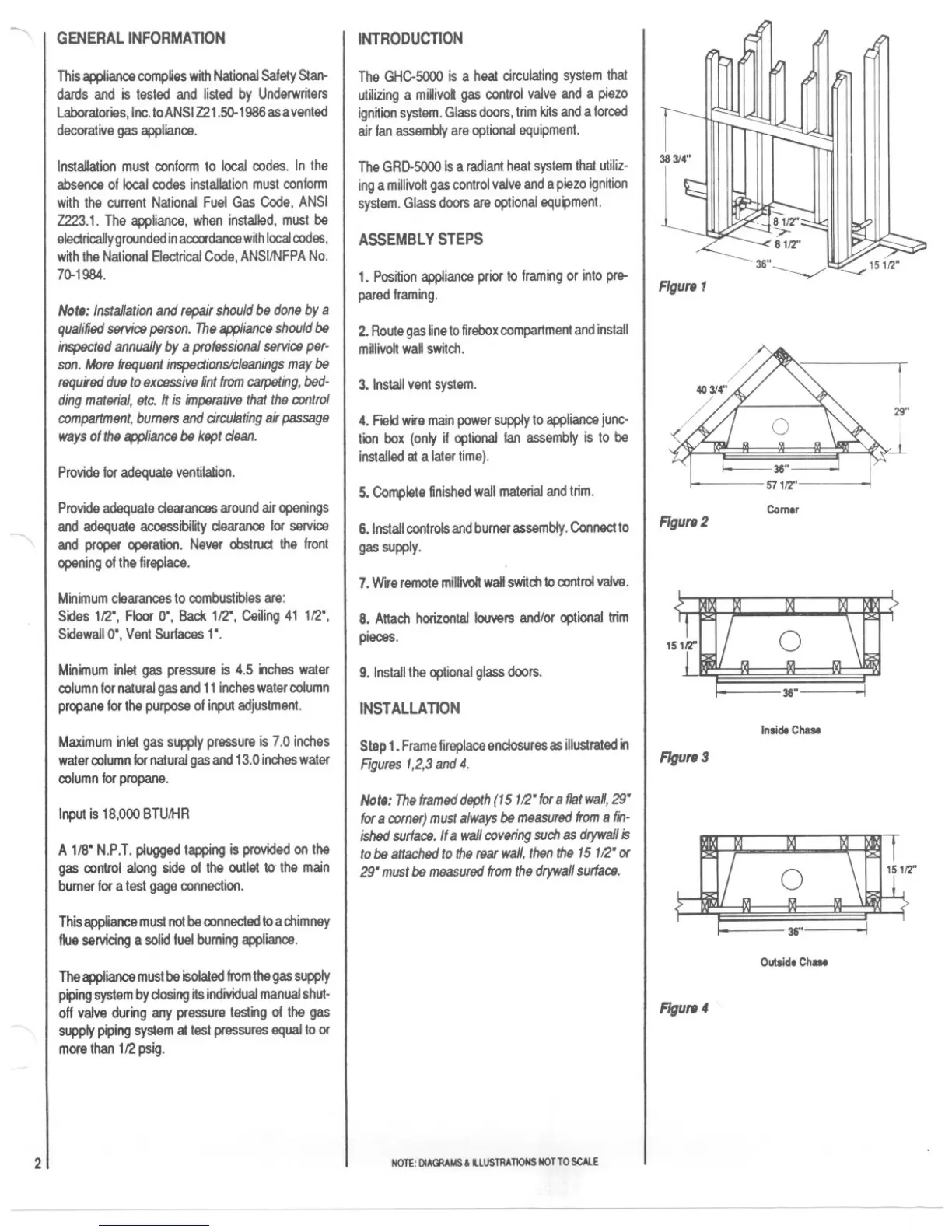
INSTALLATION
Step1. Frame fireplace endosures as illustrated in
Rgures1,2,3and4.
Note:Theframeddepth(15112"for8flatwall,29"
for8corner)mustalwaysbemeasuredfromafin-
ishedsurface.Ifa wallcoveringsuch
as drywallis
tobeattachedtotherearwall,thenthe15112"or
29"mustbemeasuredfromthedrywallsurface.
NOTE:DIAGRAMS& illUSTRATIONS NOTTO SCAlE
~
r
29"
i
~
Comer
FIgure2
36"
Inside Chase
FIgure 3
mt
36" I
Outside Chase
FIgure4