6
English
1
.3 Chimney stack - Fig. 7 ÷ 11
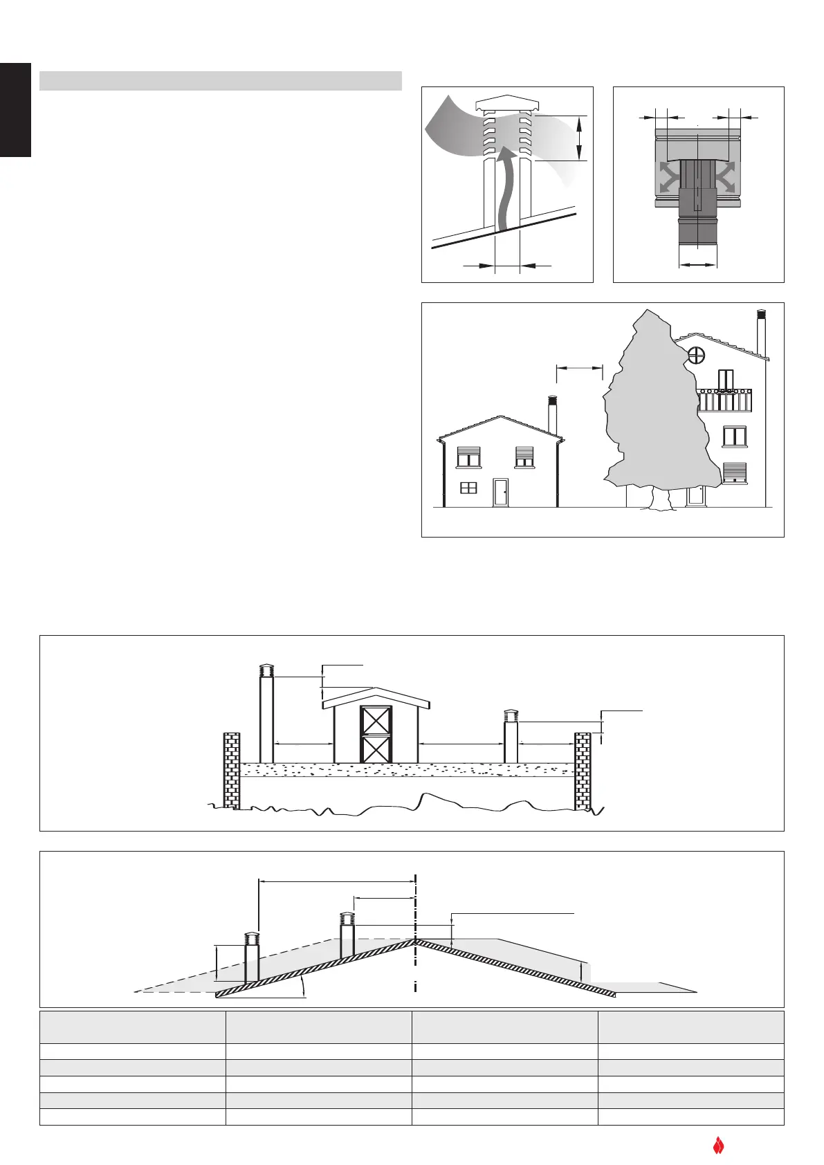
The flue must be fitted at the top with a device called a chimney stack,
d
esigned to aid dispersion of the products of combustion in the atmo-
sphere.
The chimney stack must comply with the following requirements:
-
i
t must have an internal section and shape the same as the flue;
-
it must have a useful outlet section of not less than twice that of the flue;
-
t
he part of the flue that emerges from the roof or remains in contact with the
outside (e.g. in the case of an open loft), must be covered with brick or tile ele-
ments and in any case well insulated. It must be built in such a way as to pre-
vent the penetration of rain, snow and foreign matter into the flue and to ensu-
re that in the event of winds from all directions and angle, discharge of the
combustion products is assured (chimney stack with down-draught cowl);
-
any buildings or other obstacles that are higher than the chimney stack must
not be too close to the actual stack Fig.8 - Fig.9;
-
the chimney stack must be positioned in such a way as to ensure adequate
dispersion and dilution of the products of combustion and in any case outsi-
de the reflux area.The size and shape of this area differ according to the angle
of inclination of the roof and it is therefore necessary to adopt the minimum
heights shown in Fig.10;
Example: Check the slope of the roof (column
α
), and the anticipated
distance of the chimney stack from the axis of the ridge (column A), if
the distance is greater than “A” lthe height of the chimney stack may
be read in (column H); if the distance is less than “A” the chimney stack
must rise above the ridge by 0.5 metres.
DT2030052-00
Fig. 9
TETTO PIANO
TETTO INCLINATO
0.50 m
0.50 m
0.50 m oltre il colmo
altezza zona di
reflusso Z
asse colmo
distanza maggiore A
α
H min.
distanza
min. uguale A
maggiore 5 m
pari o minore
5 m
pari o minore
5 m
DT2030053-00
Fig. 10
TETTO PIANO
TETTO INCLINATO
0.50 m
0.50 m
0.50 m oltre il colmo
altezza zona di
reflusso Z
asse colmo
distanza maggiore A
α
H min.
distanza
min. uguale A
maggiore 5 m
pari o minore
5 m
pari o minore
5 m
Fig. 11
Pitch of the roof
Horizontal width of reflux
area from ridge axis
Minimum height of
outlet from roof
Height of reflux
area
α
α
A H minimo Z
15° 1.85 m 1.00 m 0.50 m
30° 1.50 m 1.30 m 0.80 m
45° 1.30 m 2.00 m 1.50 m
60° 1.20 m 2.60 m 2.10 m
A
B*
*
B equivale al
doppio di A
DT2030051-00
Fig. 7
DT2030191-00
Fig. 8
DT2030192-00
FLAT ROOF
5 m
or less
5 m
or less
over 5 m
SLOPING ROOF
distance more than A
distance
at least A
ridge axis
0.50 abo
ve the ridge
height of
reflux area Z
* B it is twice
of to A
 Loading...