16
English
5.0 INSTALLATION
DT2010075-00
E
xternal pressure switch
• The stove is equipped with an external socket for measuring the
a
ir pressure in the flue. This verifying and checking operation
should be carried out by authorised personnel whilst the stove is
being installed.
C
overing
• Having carried out the assembly and the installation of the exter-
n
al thermostat, proceed with the assembly of the stove’s cover.
For this operation refer to the booklet entitled Instructions man-
ual ceramic cladding provided with the stove.
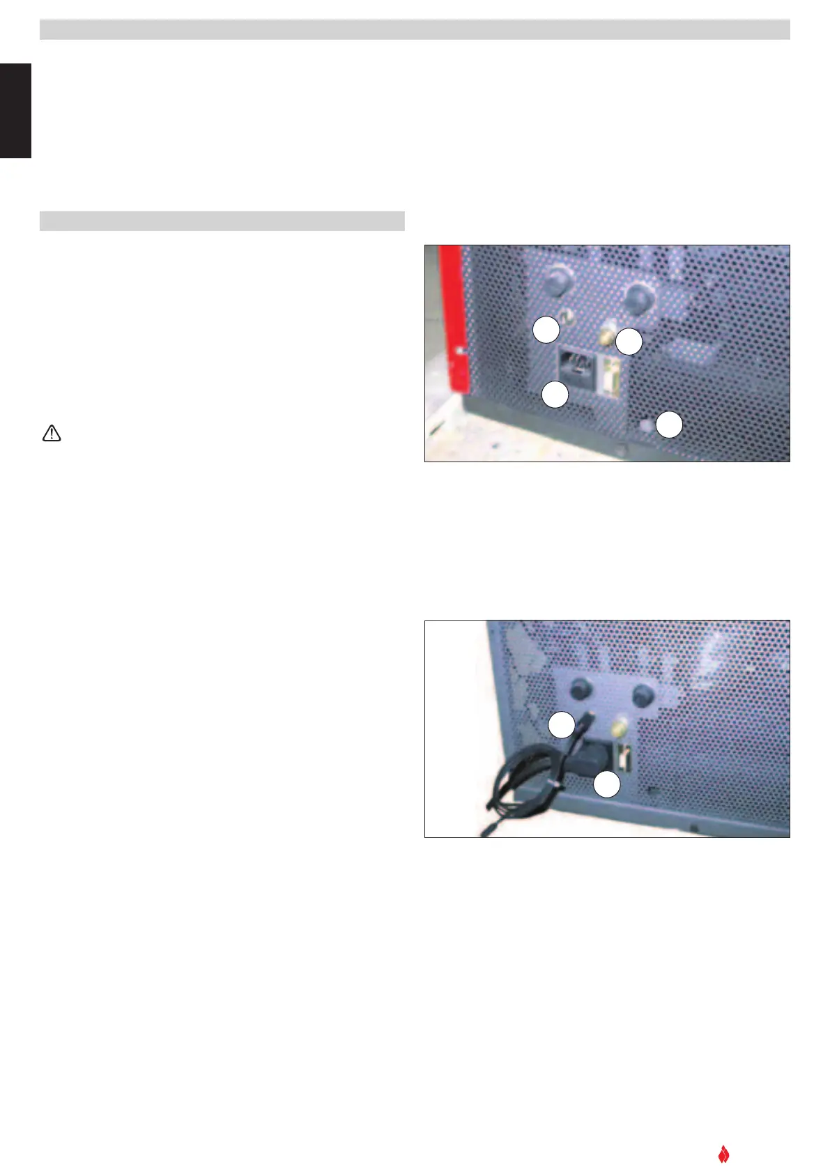
5.1 Electrical connection and the temperature sensor - Fig. 24-25
•
The stove comes equipped with a power cable which must be
connected to a 230v/50Hz supply. Connection to the rear of the
stove is illustrated in fig 25.
• The power rating is indicated in the section ‘technical character-
istics and data’ in this manual.
• According to law the installation must be earthed and include a
differential switch.
• Ensure that in its normal position the power cable does not come
into contact with any heated parts.
Ensure that the electrical socket is accessible after the
stove’s installation.
• At the same time as installing the stove, it is necessary to con-
nect the temperature sensor (provided) in the correct socket (fig
25). The sensor can be positioned as illustrated in fig 25, or
uncoil the narr
ow strip and place the sensor in a spot where a
more accurate room temperature reading can be obtained.
D
T2030074-00
F
ig. 24
DT2030075-00
Fig. 25
1
2
3
4
1 External socket for connection of temperature sensor.
2 Socket for power lead.
3 External pressure sockets.
4 Socket for inserting cable PG7 for connection of external thermostat.
5 Connecting the temperature sensor.
6 Connecting the power cable.
5
6
DT2010071-00


 To Next Page