English
17
6.0 USE
DT2010080-01
• Do not use the stove as a cooker
•
Ensure that the room in which the stove is installed is sufficient-
ly well ventilated.
• Ensure that all joints in the flue are hermetically sealed using a
silicone- (not cement-) based sealant which is r
esistant to tem
-
peratures of up to 250ºC and which shows no sign of deteriora-
tion.
• Check (or have checked) regularly that the flue is clean.
• It is
prohibited to use fuels other than pellets.
• Remove any deposits of unused pellets left by failed ignitions
before restarting the stove.
The removal of the protective grille inside the fuel tank is
strictly prohibited.
If replenishing the pellets while the stove is lit, ensure that
the bag does not come into contact with any hot sur
faces.
Keep any inflammable object well away from the stove
while it is in use (MINIMUM 100 cm fr
om the fr
ont panel).
While in use the door must r
emain closed and the glass
must be present and intact.
5
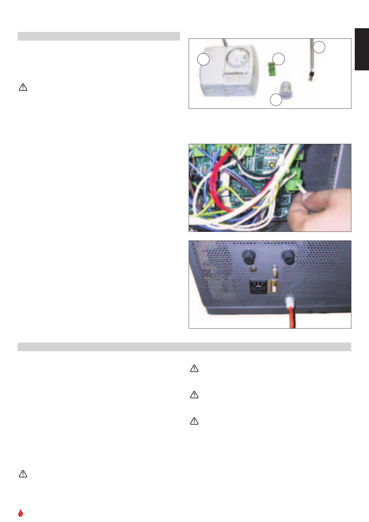
.2 Installing the external thermostat - Fig. 24 - 26 - 27 - 28
• To connect the external thermostat use cable type 2x0.5mm 2
s
topped with a PG7 connector to be inserted in the appropriate
socket in the rear panel (fig 24). This operation should be carried
out by authorised personnel.
I
nstallation can be carried out with any type of thermostat
but requires connector PG7 similar to that shown in fig 26.
T
o connect the thermostat to the electronic board, refer to
the electrical diagram.
• To install, stop the thermostat cable with connector PG7 and
insert this in the socket at the rear (fig 25 ÷ 28). Finally connect
the thermostat’s terminal to the two-pin terminal of the electron-
ic board (fig 27).
D
T2030076-00
F
ig. 26
D
T2030077-00
F
ig. 27
DT2030078-00
Fig. 28
1
2
3
4
1 Thermostat.
2 Electronic board 2-pin terminal.
3
Cable clamp.
4 Thermostat cable terminal.
DT2010035-00


 To Next Page