Agasfiex iine kit is available toaid in attachins
the directventappliance to the gassupply, This
kit can oniy be used where
local codes permit.
The
kitincludesa'h'NPTto3h'flare
in lineshut-
off valve, a12'flex line Wfemaleflare through
and a
Sg'
flare to
Sg'
NPT
fitting. The compo-
nents of this kit are rated
for both natural and
propane gas. This kit is
designed to be used as
an aid in installing the appiiance.
Brick Panel
Kit
Adecorativeceramicfiberbrickpanel
kit.Model
BSP-GR, is available to enhance the interior of
the Gas insert. install the brick refractory
pan-
eis as follows:
Remove any obstructing decorative louvers to
gain access to the gas insert door. Remove the
gas insert door. Remove the logs, log
suppori
tray and burnerassembiy along with any deco-
rative vermiculite and embers.
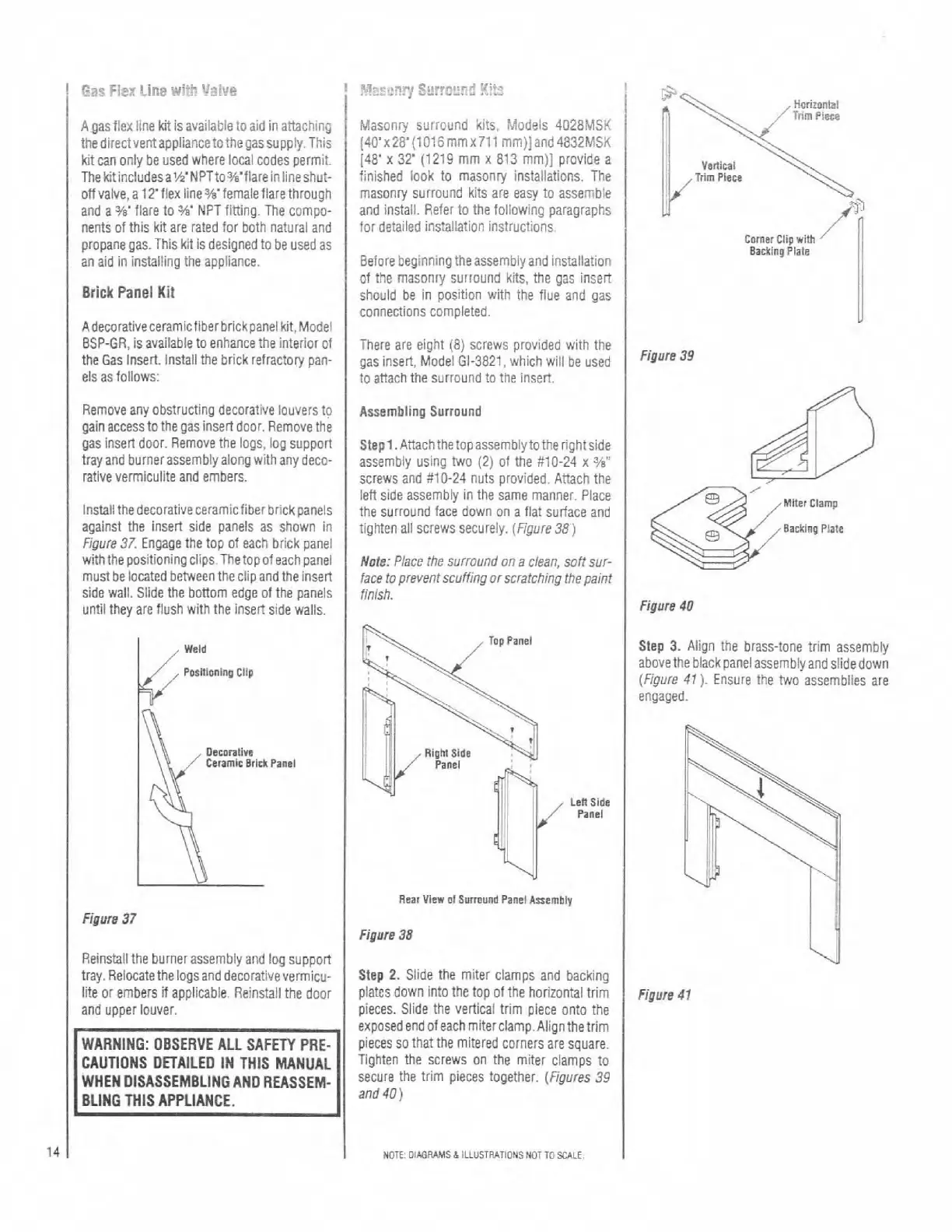
lnstailthedecorativeceramicfiberbrickpaneis
against the insert side panels as shown in
Figure 37.
Engage the top of each brick panel
with the positioning
ciips.Thetopof each panel
mustbelocated betweentheciip and the insert
side
wall. Slide the bottom edge of the panels
until they are flush with the insert side walls.
Figure
37
Reinstall the burner assembly and log supporr
tray. Relocate the logsand decorativevermicu-
iite or embers
if
applicable. Reinstall the door
and upper louver.
WARNING: OBSERVE ALL SAFEN PRE-
CAUTIONS DETAILED IN
THIS MANUAL
WHEN DISASSEMBLING AND REASSEM-
BLING
THlS APPLIANCE.
Masonry surround kits, Modeis 4028MSK
(40'~28'(10!6mmx711 mm)]and 4832MSK
[48'
x
32'
(1219 mm
x
813 mm)] provide a
finished
look to masonry installations. The
masonry surround kits are easy to
assemble
and instaii. Refer to the following paragraphs
for detailed instailation instructions.
Before beginning theassembiyand installation
of the masonry
surround kits, the gas insert
shouid be in position with the flue and gas
connections completed.
There are eight (8) screws provided with the
gas insert, Model
Gl-3821, which will be used
to attach the surround to the insert.
Assembling Surround
Step1.Attachthetopassernblytotherightside
assembly using two (2) ol the #lo-24 x
3h'
screws and #lo-24 nuts provided. Attach the
left side assembly
In the same manner. Place
the surround face down on a flat surface and
tighten ail screws securely.
(Figure38)
Mote:
Place !he surround on
a
clean, son sur-
face
to
prevent scuffing or scratching the paint
finish.
Len
Side
Panel
Rear
View
ol
Surround
Panel
Ananbly
Figure
38
Step
2.
Siide the miter ciamps and backing
plates down into the top of the horizontal trim
pieces. Slide the vertical trim piece onto the
exposed end of each
miterc1amp.Alignthetrim
pieces so that the mitered corners are square.
Tighten the screws on the miter ciamps to
secure the trim pieces together.
(Figures 39
and
40)
NOTE: OIffiUAMS
h
ILLUSTUATIONS NOT TOSCALE
Figure
39
V81tiwI
Trim
Piece
Corner
Clip
with
Miter
Clamp
Barking
Plate
Backlng
Plate
Figure
40
1
Step
3.
Align the brass-tone trim assembly
abovethe black panel assembly and slidedown
(Figure
41
).
Ensure the two assemblies are
engaged.
Figure
47