SHOULD ONLY
BE
PERFORMED
6Y
A
OUALIFIED PAOFESS!ONAL SEWICE
TECHNICIAN.
ADJUSTMENT
TO adjust the flame and position the air shutter
tothe nominal sening
(Figuie32)
and allowthe
burner to operate for at least
15
minutes.
Ob-
serve the flame. if it appears weak or sooty as
previouslydescribed,adjusttheventuriairshut-
ter until the flame appearance is as desired.
CAUTION: APPLIANCE SURFACES ARE HOT.
EXERCISE
CAUTIONTO AVOID INJURY WHILE
ADJUSTING
FLAME
APPEARANCE.
During shipment of the appliance the connec-
tion between the orifice and venturi tube can
become loose and out of aiignment. Make sure
thisconnection is tight with the orifice approxi-
mately
'/d
(6
mm) inside the venturi tube.
Note:
Any adjustments to the
air
shutter differ-
ent from those described above could cause
the
burnerassembly to malfunctionand could
void the warranty
When
satisfiedthattheappiianceoperatesprop-
eriy, proceedtofinishthe installation. Leavethe
control knob in
"ON"
position, toggle the gas
insert
ON/OFF switch "OFF."
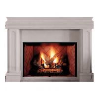
FIREPLACE FINISHES
Mantels and Trim
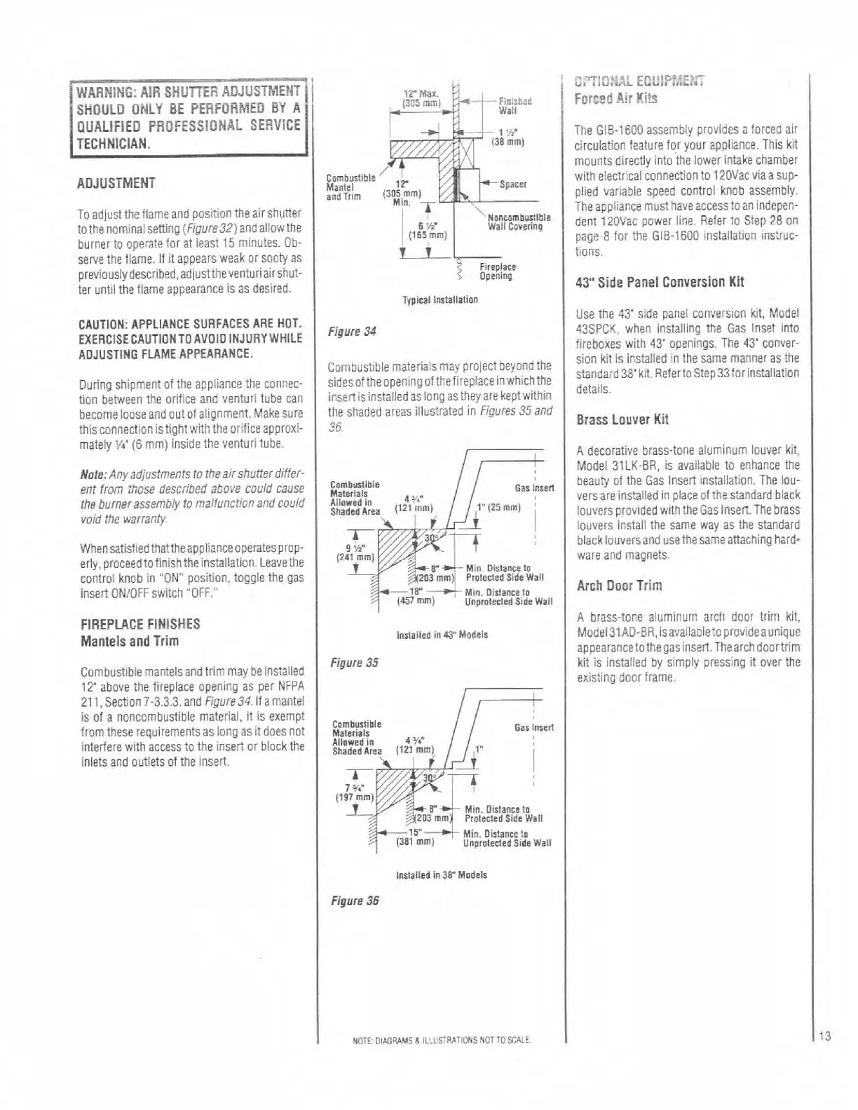
Combustible mantels and trim may be installed
12'
above the fireplace opening as per NFPA
21
1,
Section 7-3.3.3. and
figure34.
If a mantel
is of a noncombustible material,
it
is exempt
from these requirements as
long as
it
does not
interfere with access to the insert or block the
inlets and outlets of the
inseri.
Typical lmlallalion
Figure
34
Combustible materials may project beyond the
sidesoftheopen~ngofthefireplaceinwhicllthe
insert is installed as long as they are kept within
the shaded areas illustrated in
Figures35and
36
Ailowed
~n
Shaded
Arm
(Iz1
mm)
l"125
mm)
9
'h'
Figure
35
Gas
lmcrl
Min.
Dirtanm
lo
(381
mm)
unpro~ected side
Wail
lmlailcd
in38
Models
Figure
36
NOTF
DIffi%MS&
ILLUSTRATIONS
NOT
TOSCRLE
The GIB-1600 assembly provides a forced air
:irculation feature for your appliance. This kit
mounts directly into the lower intake chamber
with electrical connection to
120Vac viaa sup.
plied variable speed control knob assembly.
The appliance must have access to an indepen-
dent
120Vac power line. Refer to Step 28 on
page
8
tor the (318-1600 installation instruc-
tions.
43"
Side Panel Conversion Kit
Use the
4r
side panel conversion kit, Model
43SPCK. when installing the Gas Inset into
fireboxes
wlth
43'
openings. The 43' conver-
sion kit is Installed in the same manner as the
~tandard38'kit.RefertoStep33forinstaiiation
detaik.
Brass Louver
Kit
A decorative brass-tone aluminum louver kit,
Model 31
LK-BR, is available to enhance the
beauty of the Gas Insert instaliation. The lou-
vers are installed in place of the standard black
louvers provided with the Gas
InseC.The brass
louvers install the same way as the standard
black louversand use the same attaching hard-
ware and magnets.
Arch Door Trim
A
brass-tone aluminum arch door trim kit,
Model31AD-BR,isavaiiabietoprovideaunique
appearancetothegasinsert.Thearchdoortrim
kit is installed bv simnlv oressino it over the
,
-
existing door frame.