Duetohightemperatures,thef~replacein,which
this insert is to be insbiled shcuid be located
away from heavy traffic and away from furni-
ture and draperies.
Children and adults should be alerted to the
hazardsol
highsurfacetemperatuiesandshouid
keep away to avoid burns.
Clothing or other flammable materials should
not be placed on or near the insert.
Any fireplace in which this insert has been
installed must be vented to the outside atmo-
sphere. Do not connect this appliance to a
chimneyflueserving aseparatesolid fuel burn-
ing appliance.
Any grill, or glass panel removed for the pur-
pose
of servicing the insert must be repiaced
prior to operaling the insert.
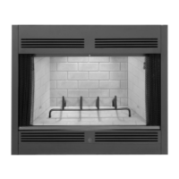
Masonry fireplaces whose front opening di-
mensions tall within defined measurements
will accept this gas insert.
INSTALLATION OPTIONS
TheGl-3821 can be installed inavarietyofways
in virtually any fireplace previously used for
burning solid fuels. The requirements of the
existing fireplace are listed on the
fronl page of
this manual. This appliance can
be
installed in
the Superiorfireplaces listed on the front page
in column two, in solid fuel burning masonry
fireplaces meeting the dimensional require-
ments listed in column
iW0, or in any other
factory-built fireplace conforming to the terms
of its listing that meets the minimal
dirnen-
sional requirements listed in column huo.
The 61-3821 is designed to be installed in
almost any approved chimney system. Figures
1.2and3show the three types of installations
to
be used withthe gas insert. Before installing
Ihe insert using any type of installation, the
existing chimney exhaust flue must be thor-
oughly cleaned and completely inspecled by
a
qualified chimney sweep or fireplace ser-
vice person.
00 not install thisappliance into
a chimney
thal is damaged without first ef-
fecting repairs that will ensure
ai!
adequate
supply of combustionairtotheappliance and
isolation of the exhaust
duct from combus-
tibles. Contact a
prolessional service penon
to make these delerminations.
iiew in!ormalion
2
each of the three types of
!as insert installations authorized to
be
used.
Jetailed installation instiuclions are provided
n the subsequent sections of this manual.
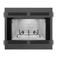
Factory-Built Fireplace lnstallation
Dvewiew
Figure 1 shows the gas insert installed in a
typical factory-built fireplace. The insert is po-
sitioned within the firebox.
A
singie
4'
(102mm) flexible duct runs from the insert
completely throughtheexisting chimney
tothe
termination installed atop a ilashing that is
secured and compietely sealed to the chimney
top. This
4'
(102 mm) flex duct conducts ex-
haust products out of the gas insert. Fresh air
for combustion enters the termination at the
top, is drawn downward through the existing
chimney's inner flue (previously used as the
exhaust) and into the gas insert via the
6'
(152
mm) flex ducting that connects the dome
adapter to the vent adapter. The dome adapter
mustbesecurely
fasteenedand completely sealed
to the fireplace dome
ceiing~
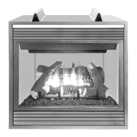
Masanry Fireplace Installation Overview
FigureZshows the gas insert lnstalied with the
masonry installation configuration. This
instal-
lat~on must be used when the masonry
fireplace's blade damper assembiy cannot
be
completely removed, preventing the dome
adapter from being installed directly to the
bottom of the flue liner.
In this type of installation, the gas insert is
positioned within
the fireplace and a pair of
flexible ducts run
from the insert completely
throughtheexistingchimneytothetermination
installed atop
a
flashing that is secured and
completely sealed to the chimney top The 3'
(76
mm) diameter fiex duct conducts exhaust
productsout of the gas inserithroughthevent
adapter. Fresh air for combustion enters the
termination at the top and is drawn downward
through the
T(51
mm) diameter fiex duct and
into the gas insert through the vent adapter.
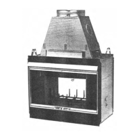
ln~s~al!a!ion
overview
(No
Damper
or
Damper
Removed)
Figure
3
shows the gas insert installed using
the optional masonry installation. This installa-
tion can oniy be used if the masonry fireplace
hasnodamperor if itsdamperassembly can
be
completely removed. In this installation, the
dome adapter must be fined directly to the
bottom of the flue liner with a complete seal.
Thisinstallation
iscompleted in the same man-
ner as the factory-built fireplace installation
using the same vent
c0mponen:s.
In this type of installation, the insert is posi-
tioned within the firebox.
Asingle
4'
(102
mm)
flexible duct runs from the insert completely
~ ~
thioughtheexistingchimneytolheterrnination
installed atoo a flashino that is secured and
-
~~~
"
completely sealed to the chimney top. This
4'
(1
02
mrn) flexduct conductsexhaust products
out of the gas insert. Fresh
air for combustion
enters the termination at the top and is drawn
downward through the existing chimney and
intothegas insertthrough
the6'(152mm)flex
ducting connecting the dome adapter to the
vent adapter. The dome adapter must be se-
curely
faslened and completely sealed lo the
bottom end of the chimney.
FACTORY-BUILT FIREPLACE
PREPARATION
IMPORTANT: BEFORE STARTING
THIS IN-
STALLATION. MAKE SURE THAT A CAS
LINE
IS EITHER INSTALLED ORCAN BEINSTALLED
~
~
TO
THE
FIREPLACE.
THISSHOULD
ONLY
BE
PERFORMED
aY
A
RUALIFIEO,
LICENSED
PLUMBER.
In order for the selected Superior fireplace to
accept the Superior gas insert, the following
steps must first be carried out:
 Loading...