Fir~place
Modi!icz!lon
Steps
Step
1.
Remove the fuel grate anC other com-
ponents if attached.
Slep
2.
Remove screens and screen rods.
Slep3. Removethe damperassembly (damper
and lintel on
RDIHCIHCE-A's).
Step
4.
Remove refractory sides and back
(metal side panels on some older
models).
Step
5.
Remove front metal ash lip (some
models).
Step 6. Increasethe height
ofthe firebox open-
ing by
cutting2'from thefrontlintel(all models
except RDMCMCE-A's).
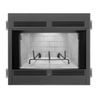
Modilication Procedures
Step
1.
Removing the Fuel Grate and/or other
Gas Appliances
Attached to Gas Line -On
most modelsthe tuei grate restson the bottom
refractory and can be
kasily removed. On other
modeisthe fuel grateis held in place by two rear
grateleg brackets.These bracketscan beeither
cut or piied off the grate legs
Remove any gas component that might be
attached
tothe gas line, sucha aiog lighteror
$
a
set
of gas logs. Be sure to a ach
a
gas cap
fitting to the open end of the gas line after the
component has been removed. This is to
as-
sure that no dirt or other debris will get into the
gas line before connecting to the gas insert.
Step
2.
Removing Screens and Rods
-
Re-
movingiwo
(2)
screwsfrom behind the upper
center of the fireplace tront frame
aiiows the
screens and screen rods to be removed from
the fireplace.
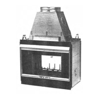
Step
3.
Removing the Damper ksembly
-
The damper blade, damper handle and linkage
can be removed by removingthree
(3)'Adnuts
from the three
(3)
botts holding the damper
blade, handle and linkage from the bracket that
Ismounted on theinnertransition. Thisapplies
to ali models except the RDIHCMCE-A models.
For
RD-A. HC-A, and HCE-A models remove
fOur(4)%e'nutSfromthe boltsthataremounted
totheinnertransitiontoallowtheentiredzmper
and lintel assemblyto be removed in one piece.
Figure
4
Step
4.
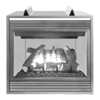
Removing the Side and Rear Relrac-
tories-There are side and rear refractories on
most Superior lireplaces
model. For
43'
and
larger systems, the removal of the rear refrac-
tory is ail that is necessary. Both side and rear
refractories must be removed lor all
38'
tire-
piacesystems. First, removetheside refractory
retainers, located at the top, middle of the
panels. Remove one panel at a time, starting
with the side refractories. On some older mod-
els there are metal side panels.
Psmive These
metal panelsflrst, thecthe rear refractorypanel.
Step
5.
Removing Front Metal Ash Lip -On
most unitsthere isasmall metai ash lip that is
securedtothefrontframe Removethe screws
in the lowerfrontfrsmethen
theash lip can be
removed. Reinstall the
tront screws.
Step 6. Cut and Remove Lintel Ertension -On
all models except the RDMCMCE-A systems.
Y(51
mm) mustbe cutoff the lower portion of
the lintel
extensian. Cufto within
l'(25
mm) of
each sidewherethe lintel
meetsthe edge ofthe
fireplace effective opening.
NOTE.
OIMPAMS
6
ILiUSTRllTlONS
NOT
TO
WLE
(3.7
ml
Min.
48
(12.2
m)
Mas.
U.S.
fmtrllltion
Only
!
Figure
5
INSTALLING
THE
GAS INSERT
The 61-3821 insert must
he
vented directly to
the outslde through its own tlexible
ducting
system;dual (side by side)
4'(102
mm) tubes
primarily configuredfor use with masonry
fire-
piaces and a concentric
4'
(1
02
mm) and
6'
(152 mm) diameter double walledvent system
primarily used in existing double
walled chim-
neys. Neither
system may sewice multiple ap-
pliances, and must
neverbe connectedtoaflue
sewing a solid fuel burning appliance.
The appliance is designed, tested and listed for
operation with, and only with, Superior Fire-
place vent components. DO
NOT
use other
manulacturer's components. The listed vent
components are identified
in
the accessories
and components section provided on page
17.
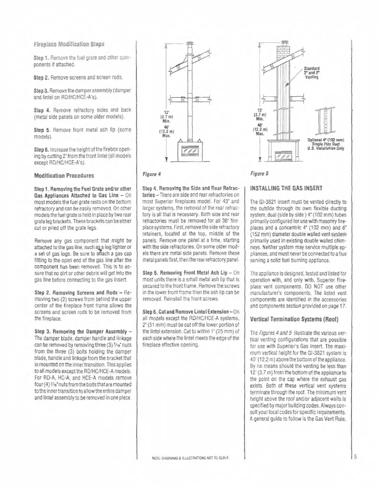
Vertical Termination
Systems
(Roof)
Tine Figures
4
and
5
illustrate the various ver-
tical venling configurations that are possible
for use with Superior's Gas Insert. The maxi-
mum vertical height
forthe 61-3821 system is
40'
[12.2m)abovethebottomoftheappliance.
By no means should the venting be less than
12'
(3.7
m) fronthe bottomof theappliance to
the point on the cap where the exhaust gas
exists. Both of these vertical vent systems
terminate through the
roof.The minimum vent
height above the
roof and/or adjacent walls is
specified
by
major building codes. Alwayscon-
suit your local codes for specific requirements.
A general guide to follow is the
Gasvent Rule.