F2s1jes*
Rule
Gas vent mps that are located
8'
(2.4 mi or
more from a
poltion of a building which ex-
tendsatanangle greaterthan 45°upwardfrom
the horizontal may terminate in accordance
with Table
1,
provided that in no case shall any
discharge opening on the cap be less than 2'
(610 mm) horizontally from the roof surface.
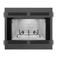
Prepare
Gas
Insert lor tnstallation
Step
1.
inspect the gas insert for any signs ~f
shipping damage. Look for bent or damaged
sheet metal components, check glass for
scratches and chipping. Inspect the gas insert
for any visual defects,
loose or missing parts.
Make sure the gas insert is compatible with
your gas type.
I
Table
1
Rooi Slope
c
Over 811 2 to 911 2
I
2'
G'
Hlinimum
Height
From
Roo?
To
Lowest Discharge Opening
Flat to 611 2
Over
6/12 to 7112
Over 711
2
to 811 2
1
G'
1'
7
1
'
fi'
- -
I
0ver14112to1fi11~
I
fi'
n'
i
Over 911 2 to 1011
2
Over10112to 11112
Over11!12to12/12
1
Over 1811
2
to 2011
2
1
7'
6'
-
I
-
2'
6'
4'
0'
Y
n'
I
Over 20112 to 21/12
1
8'
0'
set aside.
I
I
Step
2.
Remove the three
(3)
Phillips pan head
screws
located
the
lop edge
Of
the
door
and wnove the glass enclosure Panel from the
insert by tiking outward and lifting upward. Set
the panel aside and protect from inadvertent
damage. Retain screws for reassembly. Next
remove the
logs inside the appliance and also
Step
3.
Remove two
(2)
Phillips pan head
screws located at the base of each decorative
andiron leg
(Fipure6). Retain screwsfor reas-
sembly. Remove burner assembly.
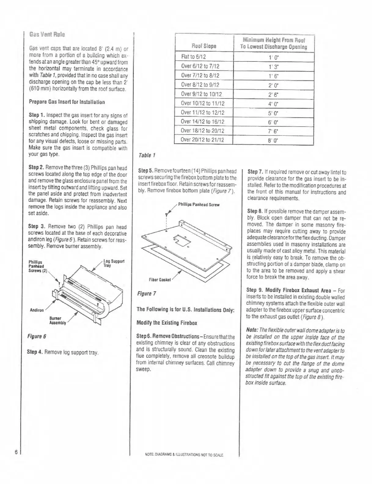
steps. Removefourteen (14) Phillips panhead
screwssecuringthefireboxbottom
platetothe
insertfireboxfloor. Retain screwsforreassem.
bly. Remove firebox bottom
(~i~,,~~
7),
/
Phllllg Panhead
Scra
Figure
6
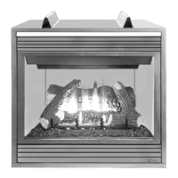
Step
4.
Remove !og support tray.
Figure
7
The Fallowing Is for
U.S.
lmtallations Only:
Modify the Existing Firebox
I
Step
6.
Remove Obstructions-Ensurethatthe
existing chimney is clear of anv obstructions
I
and is structurally sound. clean the exisin;
flue completely, remove all creosote buildup
from internal chimney surfaces. Call chimney
sweep.
Step
7.
If required remove or cut away lintel to
provide clearance
for the gas insert to be in-
stalled.
Refertothe modification procedures at
the front of this manual for instructions and
clearance requirements.
Step
8.
If possible remove the damperassem-
biy. Block open damDer that can not be re-
moved. The damper in some masonry fire-
places may require cutting away to provide
adequateclearancefortheflexducting.
Damper
assemblies used in masonry installations are
usuaily made of cast alloy metal. This material
is [eiatively easy to break. To remove the ob-
structing portion of a damper blade, clamp on
to the area to be removed and apply a shear
force to break the area away.
Step
9.
Modify Firebox Exhaust Area
-
For
insertsto be installed in existing double walled
chimney systems attach the flexibie outer wail
adapterto the firebox upper surface concentric
to the exhaust gas outlet (Figure
8).
Nole:
The flexible outer walldome adapteris to
be installed on the upper inside face of Me
existing
fireboxsurface with the flexductfacing
downforiateraitachment to the ventadapterto
be installed on the top of
thegas insert
it
may
be necessary to cut
Me
flange of the dome
adapter down to provide a snug and unob-
structed fit against the top of the existing fire-
box inside surface.