Figure
8
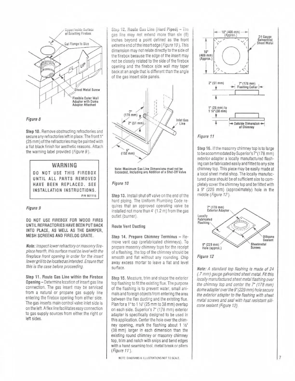
Steo
10.
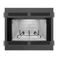
Remove obstructino refractoriesand
secureany
refractoriesieftinplace.~hefrontl'
125
mmlof the refractoriesmav be oainted with
;flat black finish for aesthetic'reaions. Attach
the warning label provided
(Fipure 9).
WARNING
DO NOT USE THIS FIREBOX
UNTIL ALL PARTS REMOVED
HAVE BEEN REPLACED. SEE
INSTALLATION INSTRUCTIONS.
PIN
901118
Figure
9
DO NOT USE FIREBOX FOR WOO0 FIRES
UNTILREFRACTORIES HAVE BEEN PUT BACK
INTO PLACE, AS WELL AS THE
DAMPER,
MESH SCREENS AN0 FIRELOG GRATE.
Note: Inspect lowerrefractory or masonry fire-
place hearth, this
surfacemust be level with the
fireplace front opening in order for the
insert
lowergrillto belocatedasintended. Ensure that
this is the case before proceeding.
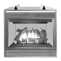
Step
11.
Route Gas Line within the Firebox
Opening- Determine location of insert gas iine
connection. The gas
insert may be sewiced
from a naturai or propane gas supply iine
entering the firebox opening from either side.
The gas inserts main control vaive inlet side is
on the
iett
Aflexiinefacili'ateseasy
connection
to gas supply sources from either the right or
left sides.
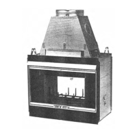
gas line may not extend more than sir
(6)
1
inches bevond a ~olnt defined as the front
/
extremeend oftheinsertedge
(Flgure
10).This
dimension may not relate directly to the side of
the firebox because the edge of the insert may
not be closely related to the side of the firebox
opening and the
tirebox side wall may taper
back at an angle that is different than the angie
of
the gas insert side panels.
Nole:
Maximum
Oat
Line Dimensions
murl
nol
be
E~ceeded,
locludinn
any
Addition
ol
a
Shul-OW
Valve
Figure
10
Step
13.
Install shutoff valve on the end of the
hard piping. The Uniform
P!urnjing Code re-
quires that an approved operating valve be
instailed not
morethan
4'
(1.2
m)from the gas
outlet (burner).
Route
Vent Ducling
Step
14.
Prepare Chimney Terminus
-
Re-
move vent cap (prefabricated chimneys). To
prepare masonry chimney
tops for the receipt
of a tiashing, the
topof the chimney shouid
be
smooth and flat wiihout any round~ng. Chip
away excess mortar to
leave a flat and level
surface.
Step
15.
Measure, trim and shape the exterior
top flashing
tofittheexistingflueThe purpose
of the flashing is to prevent water, small ani-
mals and
foreignobjectsfrom entering the area
between the flex ducting and the existing flue.
Plan fora
l'to
1
W(25
mm to38 mm) overlap
on each side. Superior's
7
(178
mmj exterior
adapter is specifically designed to be used in
thisapplication. Centerthe holeoverthe chim-
ney opening, mark the flashing about 1
'h'
(38
mm) larger in each dimension than the
existing round chimney or masonry chimney
top, trim and notch with snips and bend
edges
witha hand seaming tool. metal hreaknrpliers
(Figure
77).
NOTE:
OIAGMMS
6
ILLUS1RATIONS
NOT
TO
SCALE
24Gayge
Oalvan~red
Shre!
Metal
P
(51
mm)
7(178mm)
+
4,
Flashing
c0liariw
1'
(25
mm)
lo
1
W(38
mm)
4
~O~ideOimemionj
01
Chimney
Figure
11
Step
16.
If the masonry chimney top isto large
to beaccommodated
bySuperior's7'(178
mmi
exterior.adapter a locally manufactuied flash:
ina can
befabricatedeasilvandfined
toanvsize
"
,~
~
chimney top. This piece may be easily made at
a local sheet metal shop. The locally manufac-
tured piece should
beof sufficientsizeto com-
pletely
coverthe chimney top and befitted with
a
9'
(229
mm) (approximateiy) hole in the
middle
(Figure
17).
r
(178
mm)
Mcrior Adapter
Locally
Fabricate@
Flashing.
..--.-
Silicone
Sealant
k
n9mm]
Shaahnelal
"ole
(a~prar.)
Svewt
Figure
12
Note:
A
standard top flashing Is made of
24
(7
mm) gauge galvanized sheet meal.
Fit
this
locally
manufac!uredsheetmetalflashing
over
the chimney lop and center the
7'
(1
78
mm)
domeadapterover the9'(229mm) holesecure
the exterior
adapler to the flashing with sheet
metal screws and seal with
heat resistant sili-
cone sealant (Figure
12).