NOTE: DIAGRAMS & ILLUSTRATIONS NOT TO SCALE.
3
Gas Pressure - All Models
Tables 4, 5 & 6 show the units' gas pressure
requirements:
Inlet Gas Supply Pressure (all models)
Fuel # Minimum Maximum
Natural Gas
5.0" WC
(1.24 kPa)
10.5" WC
(2.61 kPa)
Propane
11.0" WC
(2.74 kPa)
13.0" WC
(3.23 kPa)
Table 4
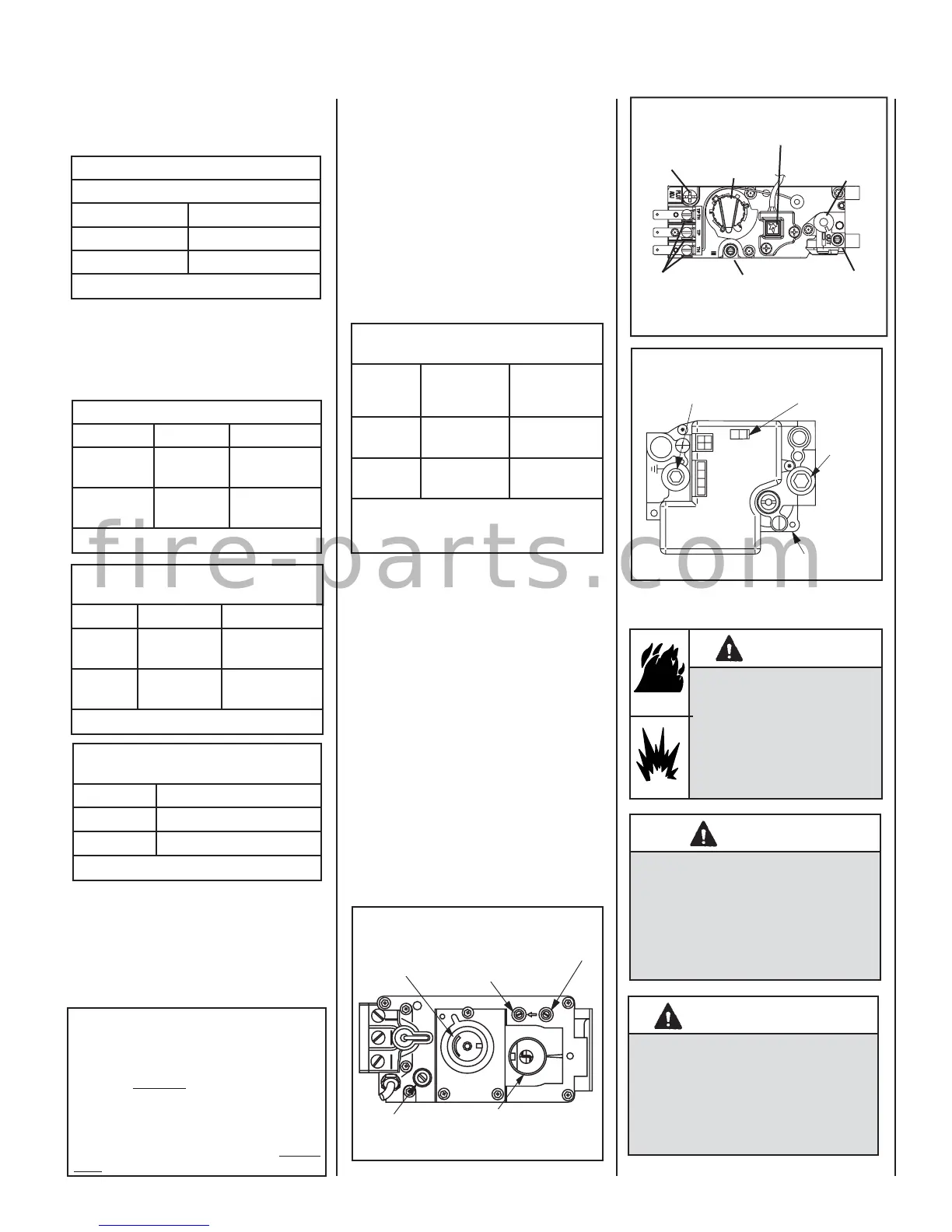
Gas Valve Diagrams
See Figures 1 & 2 for Millivolt models and
Figure 3 For Electronic Models.
Figure 3
Honeywell Electronic Gas Valve
FFO
NI
P
SI
NO
L
O
R
T
N
O
C
G
I
N
T
I
ER
Manifold Pressure
Port
ON / OFF Switch
Inlet
Pressure
Port
Electronic Gas
Control Valve
H
I
L
O
W
H
TPT
HT
P
T
P
I
L
O
T
P
I
L
O
T
O
N
it
O
F
F
IN
OUT
Manifold Pressure Tap
Inlet Pressure Tap
SIT Millivolt Gas Valve
Pilot Adjustment
Screw
HI/LO Variable
Flame Height
Adjustment
Main Gas
Control Knob
OFF/PILOT/ON
Figure 1
Orifi ce Sizes - Sea Level to High Altitude
(All Models)
These appliances are tested and approved for
installation at elevations of 0-4500 feet (0-1372
meters) above sea level using the standard burner
orifice sizes (marked with an "*" in Table 7). For
elevations above 4500 feet, contact your gas
supplier or qualifi ed service technician. Install
the appliance according to the regulations of
the local authorities having jurisdiction and, in
the USA, the National Fuel Gas Code NFPA 54
/ ANSI Z223.1 - latest edition or, in Canada, the
CAN1-B149.1 and .2 codes - latest edition.
Electronic Models with Fixed Rate Gas Valve
Natural and Propane Gas
Model Series Input Rate (BTU / HR)
SSBV-3530CNE 23,000
SSBV-4035CNE 29,000
Table 3
Burner Orifi ce Sizes
Elevation 0-4500 feet ( 0-1372 meters)
Model
Series
Natural
Gas
drill size (inches)
Propane
Gas
drill size (inches)
SSBV-3530
2.3 mm (.090")
*
37L70 •
#54 (.055")
*
99K79 •
SSBV-4035
#36 (.1065")
*
18L4001 •
#52
(.0635")
*
LB-55874D •
* Standard size installed at factory
• Part /Cat. Number
Table 7
O
N
O
F
F
P
I
L
O
T
L
O
H
I
Figure 2
GAS CONTROL
KNOB
CONVERTIBLE
HI/LO REGULATOR
(adjusts fl ame height
and heat output)
INLET
PRESSURE
TAP
PILOT
ADJUSTMENT
SCREW
WIRING
TERM-
INALS
OUTLET
PRESSURE
TAP
TP/TH
PIEZO
IGNITER
TH
TP
Honeywell Millivolt Gas Valve
Electronic Models - Electronic models have a
fi xed rate gas valve. Input of electronic models
is shown in Table 3.
MASSACHUSETTS REQUIREMENTS
These appliances are approved for installation in
the following USA locations listed below:
Installation of these fi replaces are approved
for installation in the US state of Massachu-
setts if the following additional requirements
are met -
• Installation and repair must be done by a
plumber or gas fi tter licensed in the Com-
monwealth of Massachusetts.
• The fl exible gas line connector used shall not
exceed 36 inches (92 centimeters) in length.
• The individual manual shut-off must be a
T-handle type valve.
Manifold Gas Supply Pressure
(millivolt models)
Fuel # Low High
Natural
Gas
(Lo) 2.2" WC
(.55 kPa)
(Hi) 3.5" WC
(.87 kPa)
Propane
(Lo) 6.3" WC
(1.57 kPa)
(Hi) 10.0" WC
(2.49 kPa)
Table 5
Test gauge connections are provided on the
front of the millivolt gas control valve, identi-
fi ed IN for the inlet and OUT for the manifold
side. A 1/8" NPT Test gauge connection
is provided at the inlet and outlet side of
the electronic gas control valve.
These appliances and their individual shut-off
valves must be disconnected from the gas
supply piping system during any pressure
testing of that system at pressures greater
than 1/2 psig (3.5 kPa).
These appliances must be isolated from the gas
supply piping system (by closing their individual
manual shut-off valve) during any pressure test-
ing of gas supply piping system at test pressures
equal to or less than 1/2 psig (3.5 kPa).
BTU Input - Electronic Models
SAFETY WARNIINGS
WARNING
This appliance is only for use
with the type of gas indicated on
the rating plate. This appliance
is not convertible for use with
other gases, unless a certifi ed
kit is used.
WARNING
If the information in this
manual is not followed
exactly, a fi re or explosion
may result causing prop-
erty damage, personal
injury or loss of life.
AVERTISSEMENT
Cet appareil doit être utilisé
uniquement avec les types de
gaz indiqués sur la plaque sig-
nalétique. Ne pas l'utiliser avec
d'autres gaz sauf si un kit de con-
version certifi é est installé.
Manifold Gas Supply Pressure
(electronic models)
Fuel # Max. Manifold Pressure
Natural Gas (Hi) 3.5" WC (.87 kPa)
Propane (Hi) 10.0" WC (2.49 kPa)
Table 6
f i r e - p a r t s . c o m