NOTE: DIAGRAMS & ILLUSTRATIONS NOT TO SCALE.
7
VENT TERMINATION CLEARANCES
Gas vent caps are not permitted within 8 feet
(2.4 mm) of a vertical wall or similar obstruc-
tion. Gas vent caps that are located 8' or more
from a portion of a building which extends at
an angle greater than 45° upward from the
horizontal may terminate in accordance with
(Figure 7 ), provided that in no case shall any
discharge opening on the cap be less than 2'
(610 mm) horizontally from the roof surface
(National Fuel Gas Code ANSI Z223.1 (NFPA
54) 7.6.2) (CAN/CGA B149).
Multiple Terminations
These appliances may vent adjacent to and at
the same level with any other gas appliances
(including b-vent appliances) provided that
there is at least 2 ft. (0.6m) between the proximal
edges of the vent caps. These appliances may
be vented adjacent to a chimney vent servicing
a solid fuel fi replace provided the B-vent cap
is at least 2 ft. (0.6m) away from the nearest
point of the chimney opening.
TYPICAL INSTALLATION SEQUENCE
The typical sequence of installation follows,
however, each installation is unique resulting
in variations to those described.
See the Page number references in the following
steps for detailed procedures.
Step 1. (Page 7) Construct the appliance fram-
ing.
Step 2. (Page 7) Route gas supply line to appli-
ance location.
Step 3. (Page 9) Position the appliance within
the framing and secure with nailing
fl anges.
Step 4 (Page 9) Install the vent system and
exterior termination.
Step 5. (Page 10) Field Wiring
a. Millivolt Appliances – Install the
OFF/ON burner control switch.
b. Electronic Appliances – Connect 120
VAC electrical power to the appliance
receptacle.
Step 6. (Page 11) Install the optional blower.
Step 7.(Page 11) Make connection to gas
supply.
Step 8. (Page 12) Outside Air Kit Installation.
Step 9. (Page 13) Checkout appliance opera-
tion.
Step 10. (Page 14) Install volcanic stone,
embers and logs.
Step 11. (Page 17) Install glass enclosure
panel.
Step 12 (Page 17) Adjust burner primary air
shutter to achieve proper fl ame appear-
ance.
Step 13. (Page 18) Spillage Test and (safety
limit) Switch Operation.
Step 14. (Page 19) Install the decorative trim
and hood.
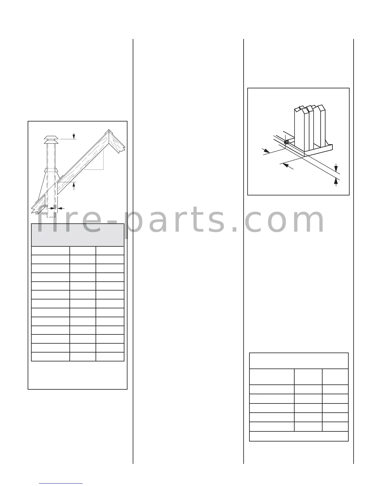
Termination Heights For Vents
Above Flat Or Sloped Roofs
Ref. NFPA 54 / ANSI Z223.1, 7.6
Roof Pitch Feet Meters
Flat to 6/12 1.0 0.3
6/12 to 7/12 1.25 0.38
7/12 to 8/12 1.5 0.46
8/12 to 9/12 2.0 0.61
9/12 to 10/12 2.5 0.76
10/12 to 11/12 3.25 0.99
11/12 to 12/12 4.0 1.22
12/12 to 14/12 5.0 1.52
14/12 to 16/12 6.0 1.83
16/12 to 18/12 7.0 2.13
18/12 to 20/12 7.5 2.29
20/12 to 21/12 8.0 2.44
Figure 7 - Vertical Vent Termination Clearances
Roof Pitch is X/12
Minimum Height from Roof to
Lowest Discharge Opening
X
12
1" (25 mm)
Minimum
Note: Venting terminals shall not be recessed
into a wall or siding.
Gas Vent Rule
Step 1. FRAMING
Frame these appliances as illustrated in Figure
9. All framing details must allow for a minimum
clearance to combustible framing members as
shown in Table 8 on Page 6.
If the appliance is to be elevated above fl oor
level, a solid continuous platform must be
constructed. Headers may be in direct contact
with the appliance top spacers but must not
be supported by them or notched to fi t around
them. All construction above the appliance must
be self supporting, DO NOT use the appliance
for structural support.
Side Nailing Flanges
The fi replace should be secured to the framing at
the side(s) of the unit using the factory-provided
nailing fl anges. Install the 8 nailing fl anges as
shown in Figure 10 using the existing screws.
Position the fi replace within the framing. When
required, the tabs may be bent 90 degrees by
hand or with the assistance of a hammer. Use
wood screws to secure the nailing fl anges to the
framing. See Table 8 on Page 6 for clearances
of framing members to cabinet parts. The nailing
fl ange itself can directly contact framing.
Step 2. Routing Gas Line
Route a gas line along the inside of the right side
framing as shown in Figure 8. Gas lines must
be routed, constructed and made of materials
that are in strict accordance with local codes
and regulations.
Schedule 40 (black iron) Pipe
Inside Diameter (Inches)
Schedule 40 Pipe
Length (feet)
Natural
Gas
Propane
Gas
0-10 1/2 3/8
10-40 1/2 1/2
40-100 1/2 1/2
100-150 3/4 1/2
150-200 3/4 1/2
Table 9
Proper Sizing of Gas Line
Properly size and route the gas supply line
from the supply regulator to the area where the
appliance is to be installed per requirements
outlined in the National Fuel Gas Code, NFPA
54 - latest edition (USA) or B149 - latest edition
(Canada). Never use galvanized or plastic pipe.
Refer to Table 9 for proper sizing of the gas
supply line, if black iron pipe is being used. Gas
lines must be routed, constructed and made
of materials that are in strict accordance with
local codes and regulations. We recommend
that a qualifi ed individual such as a plumber
or gas fi tter be hired to correctly size and route
the gas supply line to the appliance. Installing
a gas supply line from the fuel supply to the
appliance involves numerous considerations of
materials, protection, sizing, locations, controls,
pressure, sediment, and more. Certainly no one
unfamiliar and unqualifi ed should attempt sizing
or installing gas piping.
Also see
Figure 9
6 1/2"
(152 mm)
3"
(76 mm)
Figure 8- ROUTE GAS LINE
Right Side Front Corner of
Fireplace Framing
f i r e - p a r t s . c o m