AOC-USASLP-L8i Add-on Card User’s Manual
2-2
2-2 Front Jumper Locations and Pin Definitions
To modify the operation of the backplane, jumpers can be used to choose between
optional settings. Jumpers create shorts between two pins to change the function of the
connector. Pin 1 is identified with a square solder pad on the printed circuit board.
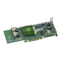
Figure 2-2 shows jumper locations for the add-on card, while Table 2-2 lists the add-on
card’s pin definitions.
Figure 2-2. Jumper Locations
Table 2-2. SWR5 Jumper Settings
Jumper Jumper Settings Note
SWR5
1-2: Enabled
3: Disabled
Leave disabled when operating in IR or IT mode. Enable for SR
mode operation. Default setting is disabled for IT mode (see
Chapter 3).
SWR5
Connector
Pins
Jumper
Setting
3 2 1
3 2 1
 Loading...