ContaCt InformatIon
• www.supermicro.com (Email: support@supermicro.com)
• Manuals: http://www.supermicro.com/support/manuals
• Drivers & Utilities: ftp://ftp.supermicro.com
• Safety: http://www.supermicro.com/about/policies/safety_information.cfm
The C7Z270-CG supports a 6
th
and 7
th
generation Intel
®
Core
TM
i7/i5/i3 processor, up to 64GB of Unbuffered (UDIMM)
non-ECC DDR4 memory, up to 3733 MHz (OC) in four 288-pin memory slots. Populating these DIMM slots with
a pair of memory modules of the same type and same size will result in interleaved memory, which will improve
memory performance.
Note: 1) For memory optimization, use only DIMM modules that have been validated by Supermicro. For the latest memory updates, please
refer to our website at http://www.supermicro.com/products/motherboard.
2) Always connect the power cord last, and always remove it before adding, removing or changing any hardware components.
LED Indicators
LED Description Color/State Status
LED1 Onboard Standby PWR LED Green: Solid on Power On
LED2 M.2 connector 2 SSD ACT LED Green: Solid on M.2 device connected
LED3 M.2 connector 1 SSD ACT LED Green: Solid on M.2 device connected
LED4 Status Code LED Digital Readout See manual
LED indicators
CPU & Memory Support
CPU & Memory Support
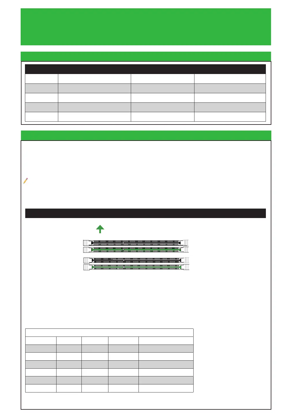
Towards the CPU
Memory Population Guidelines
When installing memory modules, the DIMM slots should be populated in the following order: DIMMA2, DIMMB2,
then DIMMA1, DIMMB1.
• Always use DDR4 DIMM modules of the same size, type and speed.
• Mixed DIMM speeds can be installed. However, all DIMMs will run at the speed of the slowest DIMM.
Recommended Population (Balanced)
DIMMB2 DIMMA2 DIMMB1 DIMMA1 Total System Memory
4GB 4GB 8GB
4GB 4GB 4GB 4GB 16GB
8GB 8GB 16GB
8GB 8GB 8GB 8GB 32GB
16GB 16GB 32GB
16GB 16GB 16GB 16GB 64GB
DIMMB2 (Green Slot)
DIMMA2 (Green Slot)
DIMMA1 (Black Slot)
DIMMB1 (Black Slot)
DIMM Memory Installation

 Loading...


