MNL-1909-QRG-100
© 2017 Supermicro Computer Inc. All rights reserved. Reproduction of this document whether in part or in whole is strictly prohibited without Super-
micro's written consent. All Trademarks are property of their respective entities. All information provided is deemed accurate at the time of printing;
however, it is not guaranteed.
Notes
• Graphics shown in this quick reference guide are for illustration only. Your components may or
may not look exactly the same as drawings shown in this guide.
• Refer to Chapter 2 of the User Manual for detailed information on jumpers, connectors, LED
indicators, memory support and CPU/motherboard installation instructions.
Power Butt
LED
1
NIC1 LED
Reset Button
2
HDD LED
Power LED
Reset
PWR
Vcc
Ground
Ground
X
X
Vcc
Vcc
Vcc
X
X
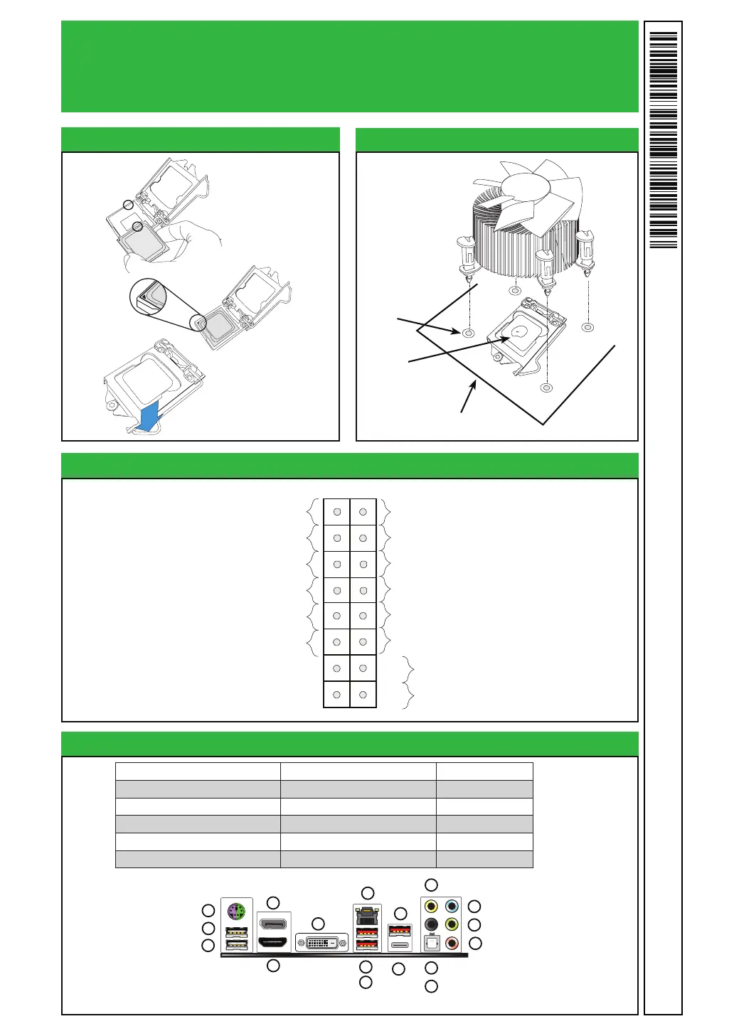
Front Panel Control (JF1)
CPU Installation
Heatsink Installation
Heatsink
with Fan
Motherboard
Mounting Hole
Back Panel I/O Connectors
A. PS/2 Keyboard/Mouse Port G. Gb LAN Port 1 M. Surround Out
B. USB 2.0 Port 0 H. USB 3.1 Port 8 N. S/PDIF Out
C. USB 2.0 Port 1 I. USB 3.1 Port 9 O. Line In
D. Display Port J. USB 3.1 Port 10 P. Line Out
E. HDMI Port K. USB 3.1 Port 11 (Type C) Q. Mic In
F. DVI Port L. Center/LFE Out
G
H
I
J
K
L
O
P
Q
A
B
C
D
E
F
M
N
C7Z270-CG
Add
thermal paste

 Loading...


