Do you have a question about the Supermicro H11SSL-I and is the answer not in the manual?
Guidelines for handling static-sensitive components to prevent damage.
Instructions for installing the motherboard into the chassis, including mounting holes.
Step-by-step guide for installing the CPU and heatsink assembly.
Information on memory types, population guidelines, and installation procedures.
Provides steps for diagnosing and resolving common system issues before and after power-on.
Step-by-step instructions for recovering the UEFI BIOS using a USB device.
| ECC | Yes |
|---|---|
| Memory voltage | 1.2 V |
| Memory channels | Octa-channel |
| Memory slots type | - |
| Supported memory types | DDR4-SDRAM |
| Maximum internal memory | 1024 GB |
| Supported memory clock speeds | 2666 MHz |
| USB 2.0 ports quantity | USB 2.0 ports have a data transmission speed of 480 Mbps, and are backwards compatible with USB 1.1 ports. You can connect all kinds of peripheral devices to them. |
| USB 3.2 Gen 1 (3.1 Gen 1) Type-A ports quantity | 2 |
| Number of DIMM slots | 8 |
| PCI Express x8 (Gen 3.x) slots | 3 |
| Supported DIMM module capacities | 8GB, 16GB, 32GB, 64GB, 128MB |
| BIOS type | AMI |
| ACPI version | 5.1 |
| BIOS memory size | 128 Mbit |
| Wi-Fi | No |
| LAN controller | Intel I210, Realtek RTL8211E |
| Ethernet interface type | Gigabit Ethernet |
| On-board graphics card model | Aspeed AST2500 |
| Bundled software | Super Doctor 5 Watch Dog NMI SUM IPMI 2.0, KVM w/ dedicated LAN |
| Storage temperature (T-T) | -40 - 70 °C |
| Operating temperature (T-T) | 10 - 35 °C |
| Storage relative humidity (H-H) | 5 - 95 % |
| Operating relative humidity (H-H) | 8 - 90 % |
| Component for | Server |
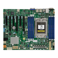
| Motherboard form factor | ATX |
| Number of SATA III connectors | 12 |
| Trusted Platform Module (TPM) version | 1.2 |
| Processor socket | Socket SP3 |
| Processor manufacturer | AMD |
| Compatible processor series | AMD EPYC |
| Supported storage drive interfaces | SATA III |
| Harmonized System (HS) code | 84733020 |
| Depth | 244 mm |
|---|---|
| Width | 305 mm |