39
Chapter 2: Installation
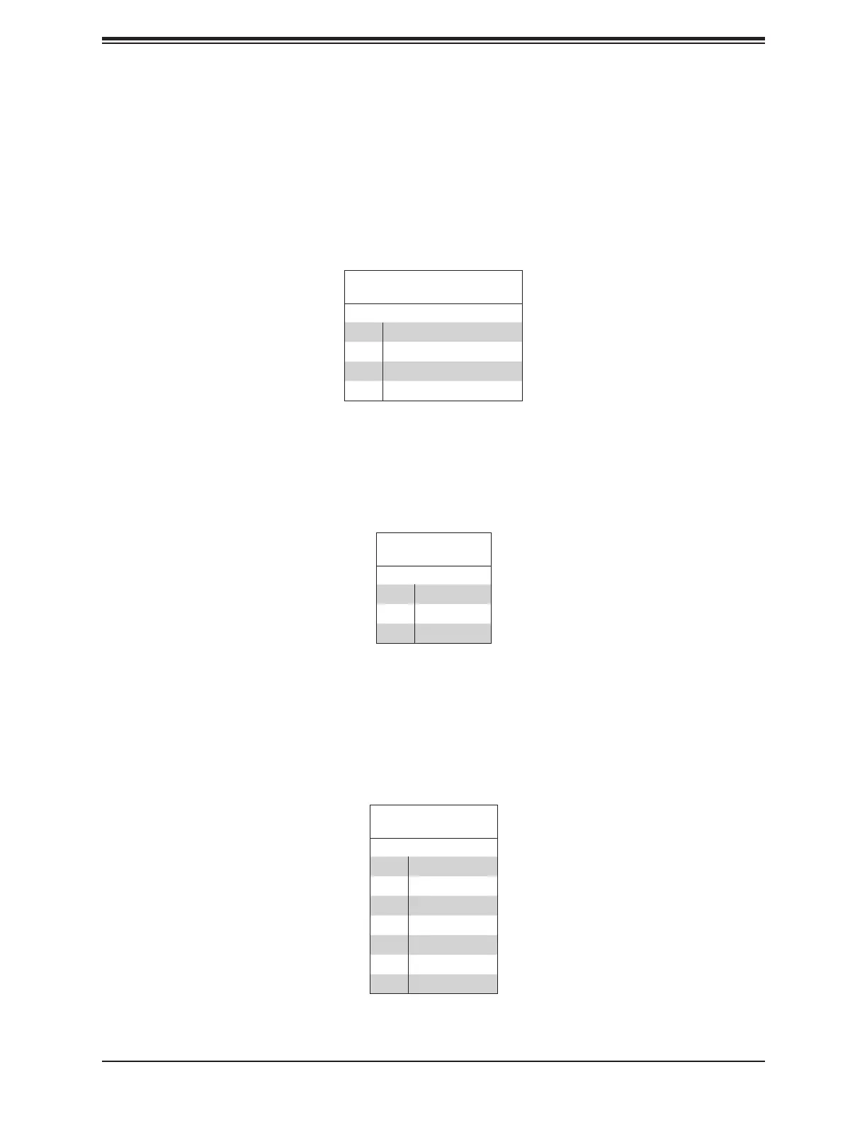
Onboard Fan Headers (FAN1~FAN5, FANA, FANB)
There are seven fan headers on the motherboard. These are 4-pin fan headers; pins 1-3
are backward compatible with traditional 3-pin fans. The onboard fan speeds are controlled
by Thermal Management (via Hardware Monitoring) in the BMC. When using Thermal
Management setting, please use all 4-pin fans.
Fan Header
Pin Denitions
Pin# Denition
1 Ground (Black)
2 +12V (Red)
3 Tachometer (Yellow)
4 PWM Control (Blue)
Disk-On-Module Power Connector (JSD1 & JSD2)
The Disk-On-Module (DOM) power connector at JSD1 provides 5V power to a solid-state DOM
storage device connected to one of the SATA ports. See the table below for pin denitions.
DOM Power
Pin Denitions
Pin# Denition
1 5V
2 Ground
3 Ground
I-SATA Ports (I-SATA0~I-SATA15), H11SSL-i Only
The H11SSL Motherboard Series has sixteen (16) available SATA 3.0 ports (SATA0~15) on
the motherboard. SATA0~SATA7 are standard SATA 3.0 ports. SATA8~SATA11 (JNVME0)
and SATA12~SATA15 (JNVME1) support SATA 3.0 drives, requiring a break-out cable.
SATA Connectors
Pin Denitions
Pin# Signal
1 Ground
2 SATA_TXP
3 SATA_TXN
4 Ground
5 SATA_RXN
6 SATA_RXP
7 Ground
2.7 Connectors
 Loading...