Do you have a question about the Supermicro H12SSL Series and is the answer not in the manual?
Provides a quick reference table for jumpers, LEDs, and connectors on the motherboard.
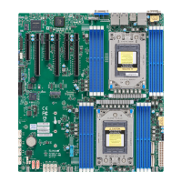
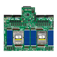
Details the AMD EPYC processor and chipset features, including architecture and capabilities.
Covers system health monitoring features and recovery from AC power loss.
Explains onboard voltage monitors, fan control, temperature monitoring, and alerts.
Describes Advanced Configuration and Power Interface features for system and peripheral power management.
Highlights the importance of a stable power source for reliable system operation.
Details the Super I/O chip's capabilities for serial communication and power management.
Provides precautions for handling static-sensitive devices to prevent damage during installation.
Guides on aligning mounting holes, using standoffs, and securing the motherboard in the chassis.
Step-by-step instructions for installing the CPU and heatsink, including socket handling.
Details memory support specifications and provides guides for DIMM installation and population.
Identifies and describes the various input/output ports located on the rear of the motherboard.
Explains the pin definitions for the front control panel connector (JF1).
Describes onboard fan headers, SATA ports, SAS ports, and NVMe Express connections.
Explains how jumpers work and details settings for Clear CMOS, VGA, and SAS enable/disable.
Describes the meaning of LAN port LEDs, UID switch LED, BMC heartbeat, and power OK LEDs.
Offers systematic procedures for diagnosing and resolving common system issues like no power or no video.
Outlines steps for contacting technical support, including required information and distributor contact.
Addresses common user queries regarding memory support, BIOS updates, and OS installation issues.
Explains the process for obtaining warranty service, including RMA procedures and conditions.
Provides detailed instructions for removing and installing the onboard CMOS battery, including disposal.
Introduces the AMIBIOS setup utility and explains navigation methods.
Details the Main BIOS setup screen, including system date, time, BIOS version, and memory information.
Covers advanced BIOS settings such as boot features, CPU configuration, and I/O settings.
Configures Intelligent Platform Management Interface settings for remote access and monitoring.
Manages SMBIOS Event Log settings, including enabling, disabling, and erasing log entries.
Configures security settings like administrator passwords, password checks, and secure boot options.
Sets boot mode, boot order priorities, and UEFI application boot priorities.
Explains options for discarding changes, saving changes, restoring defaults, and exiting the BIOS setup.
Guides on installing the Windows OS, including driver loading and boot device selection.
Provides instructions for downloading and installing system drivers and utilities from the Supermicro website.
Describes SuperDoctor 5 for system health monitoring, alerts, and remote management.
Covers IPMI features for remote access, monitoring, and management, including BIOS settings.
Warns about the danger of explosion from incorrect battery replacement and proper disposal.
Advises on proper disposal of the product according to national laws and regulations.
Provides an overview of the Unified Extensible Firmware Interface (UEFI) and its role.
Explains the UEFI BIOS flash chip structure and the recovery process for corrupted BIOS images.
Details the steps for recovering the BIOS block using a USB-attached device.
| Socket | Socket SP3 |
|---|---|
| CPU Series | AMD EPYC 7002/7003 Series |
| Chipset | AMD SoC |
| Memory Support | DDR4 ECC Registered DIMM |
| Memory Slots | 8 DIMM slots |
| Maximum Memory Capacity | 2TB |
| PCIe Slots | 7 x PCIe 4.0 x16 slots |
| Networking | Dual 10GBase-T with Intel X550-AT2 |
| Storage | 2x M.2 slots, M-Key, 2280/22110, PCI-E 4.0 x4 |
| USB Ports | 4 x USB 3.0, 2 x USB 2.0 |
| Power Connectors | 24-pin ATX, 2 x 8-pin EPS |