EasyManuals Logo

Supermicro H12SSL Series User Manual

Supermicro H12SSL Series
100 pages
To Next Page IconTo Next Page
To Previous Page IconTo Previous Page
Page #10 background imageLoading...
Page #10 background image
10

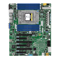
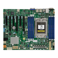
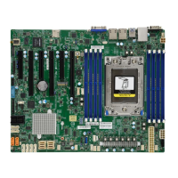
Figure 1-2. H12SSL-i/C/CT/NT Layout
1.1 Quick Reference
USB0/1
COM1
JPG1
JNCSI1
JTPM1
USB4/5
JF1
LE1
L-SAS4-7
L-SAS0-3
I-SATA0
I-SATA1
JSD1
JSD2
JL1
SATA8~15
I-SATA2/3
JD1
JSTBY1
SGPIO1
JPS1
JOH1
JUID
FAN1
JPI2C1
JPWR2
JPWR1
IPMI LAN
USB2/3
LAN1
LAN2
VGA
UID-SW
UID-LED
BT1
JPL1
JWD1
M.2-M2
M.2-M1
I-SATA4/5
I-SATA6/7
FAN4
FAN3
FANB
FAN2
FANA
SATA0~7
SGPIO2
PCIe Slot 1
PCIe Slot 2
PCIe Slot 3
PCIe Slot 4
PCIe Slot 5
PCIe Slot 6
PCIe Slot 7
JPWR3
DIMMD1
DIMMC1
DIMMB1
DIMMA1
DIMME1
DIMMF1
DIMMG1
DIMMH1
JIPMB1
JCFG2
JCFG1
FAN5
JNVMe0
JNVMe1
JBT1
LEDM1
LEDSAS

Table of Contents

Questions and Answers:

Question and Answer IconNeed help?

Do you have a question about the Supermicro H12SSL Series and is the answer not in the manual?

Supermicro H12SSL Series Specifications

General IconGeneral
SocketSocket SP3
CPU SeriesAMD EPYC 7002/7003 Series
ChipsetAMD SoC
Memory SupportDDR4 ECC Registered DIMM
Memory Slots8 DIMM slots
Maximum Memory Capacity2TB
PCIe Slots7 x PCIe 4.0 x16 slots
NetworkingDual 10GBase-T with Intel X550-AT2
Storage2x M.2 slots, M-Key, 2280/22110, PCI-E 4.0 x4
USB Ports4 x USB 3.0, 2 x USB 2.0
Power Connectors24-pin ATX, 2 x 8-pin EPS

Related product manuals