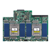
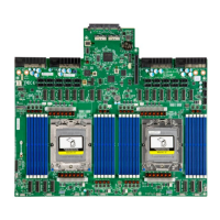
The H13DSG-O-CPU is a high-performance server motherboard designed for system integrators, IT technicians, and knowledgeable end-users. It is built upon the functionality and capability of Dual AMD EPYC™ 9004 series processors in SP5 sockets, offering maximum I/O expandability, energy efficiency, and data reliability in a 5-nm process architecture. This motherboard is optimized for embedded storage solutions, networking applications, and cloud-computing platforms, drastically increasing system performance for a multitude of server applications.
Function Description:
The H13DSG-O-CPU motherboard serves as the central component for high-performance server systems, supporting dual AMD EPYC™ 9004 series processors. It integrates advanced features for system health monitoring, power management, and extensive I/O capabilities. The board is designed for professional installation and service, ensuring robust operation in demanding environments.
Important Technical Specifications:
- CPU: Supports Dual AMD EPYC™ 9004 series processors in SP5 sockets.
- Memory:
- Up to 6TB registered ECC DDR5 4800 MT/s speed.
- 24 DIMM slots.
- Supports DIMM sizes up to 256GB.
- Memory Interleaving: Controls fabric level memory interleaving, with options for Disabled and Auto.
- Chipset Interleaving: Controls interleave memory blocks across the DRAM chip for node 0, with options for Disabled and Auto.
- BankSwapMode: Options include Auto, Disabled, and Swap CPU.
- Power Down Enable: Options include Disabled, Enabled, and Auto.
- DRAM Scrub Time: Configurable from Disabled to 48 hours.
- TSME (Transparent SME): Options include Auto, Enabled, and Disabled.
- Enhanced PPR: Enables a full memory test, with options for Disabled and Enabled.
- Memory Target Speed: Options include Auto, DDR3200, DDR3600, DDR4000, DDR4400, DDR4800, DDR5200, and DDR5600.
- Chipset: System on Chip (SoC).
- Expansion Slots:
- 128-Lane PCIe 5.0 x8 MCIO interfaces to GPU baseboard.
- 32-Lane PCIe 5.0 x8 MCIO interfaces for GPU baseboard, NVMe, or OCP NIC.
- Up to 4 xNVMe (x4) ports.
- OCP 3.0 NIC slot (AIOM slot) with NCSI interface.
- PCIe Port Bifurcation Configuration: Options include Auto, x4x4x4x4, x4x4x8, x8x4x4, x8x8, and x16 for various CPU PCIe Package Groups (P2, G2, P3, G3, P1, G1, P0, G0).
- Network:
- ATEN IPMI from ASPEED BMC for one gigabit RJ45 port via AOM-PTG-I2T.
- OCP 3.0 NIC slot with NCSI interface via AIOM slot.
- Intel(R) Ethernet Controller X710 for 10GBASE-T.
- Network Stack: Options to Disable or Enable UEFI Network Stack.
- IPv4/IPv6 PXE Support: Options to Disable or Enable.
- IPv4/IPv6 HTTP Support: Options to Disable or Enable.
- PXE Boot Wait Time: Configurable (default 0).
- Media Detect Count: Configurable (default 1).
- MAC Address Configuration: Configured (Disabled/Enabled), Interface ID, DAD Transmit Count, Policy (automatic/manual).
- Graphics: Aspeed AST2600 BMC chip with one VGA port via AOM-PTG-I2T.
- I/O Devices:
- Two SATA 3.0 ports (SATA0~SATA1) supported by ASMEDIA ASM1061.
- Four NVMe ports.
- One USB 2.0 header for front control panel (USB2/3).
- BIOS:
- 256Mb SPI AMI BIOS® SM Flash UEFI BIOS.
- ACPI 6.4, SMBIOS 3.5 or later.
- Plug-and-Play (PnP).
- RTC (Real Time Clock) wakeup.
- Riser Card Auto-Detection Support.
- Power Management:
- ACPI power management (S5).
- Wake-On-LAN.
- Power-on mode for AC power recovery (Stay Off, Power On, Last State).
- System Health Monitoring:
- Onboard voltage monitoring for +3.3V, +5V, +12V, +3.3VStb, +5Stb.
- Onboard temperature monitoring for CPU, System, Memory, and Peripheral.
- CPU Thermal Trip support.
- Fan Control:
- Ten 4-pin fan headers.
- Fan speed control.
- System Management:
- IPMIView/SMCIPMITOOL/IPMICFG.
- SuperDoctor® 5.
- SDO/SPM/SSM/SUM-OOB/InBand.
- Trusted Platform Module (TPM) support.
- LED Indicators:
- CPU / System Overheating.
- Power / Suspend-state Indicator.
- Fan Failure.
- UID / Remote UID.
- M.2 Active LEDs (LED4): Green when device active or M.2 SATA device detected.
- Dimensions: 17" (W) x 14.7" (L), (431.80 mm x 373.38 mm).
- Connectors:
- JPW1~JPW4: 12V power sources.
- BP_PWR1~3: 8-pin 12V DC power inputs for backplane.
- GPU_PWR1~20: 8-pin 12V DC power inputs for GPUs.
- JIPMB1: 4-pin External I2C Header (for IPMI card).
- AIOM: Supermicro Advanced I/O Module.
- JSLOT1: Supermicro I/O Riser Slot (AOM-PIO-i2G).
- JMCIO-RA1/JMCIO-RA2: AIOM Input.
- USB2/3 (2.0): Front Side Pin Header.
- FAN1~FAN10: 4-pin System/CPU Fan Headers.
- JF1: Front Control Panel Header.
- SATA0~SATA1: SATA 3.0 Ports.
- S1: For System Configuration.
- JNCSI1~2: NCSI.
- JL1: Chassis Intrusion Header.
- JTPM1: Trusted Platform Module/Port 80 Connector.
- Jumpers:
- JBT1 (CMOS Clear): Open (Normal) by default.
- JPFR3 (PFR Function): Open (Normal) by default.
Usage Features:
- Easy Installation: Standard mounting holes for various chassis types. Metal standoffs are recommended for grounding.
- Processor Installation: Requires a T20 screwdriver for CPU socket operations. Processors are installed with a carrier frame, and heatsinks are secured with a diagonal tightening pattern using a torque screwdriver (12.5~15.0 kgfcm).
- Memory Installation: DIMMs are inserted into slots by pushing release tabs outwards, aligning the key and notches, and pressing down until they snap into place.
- Front Control Panel: JF1 header supports power switch, reset switch, power fail LED, UID LED, NIC LEDs, HDD LED, and NMI switch.
- BIOS Configuration: UEFI BIOS provides extensive settings for CPU, memory, ACPI, PCIe, USB, network, and security.
- System Monitoring: Onboard hardware monitor chip continuously scans voltage levels, fan speeds, and temperatures, providing warnings or error messages. Real-time readings are displayed in BMC.
- Power Recovery: BIOS setting allows the system to automatically return to the power-on state or remain off after an AC power loss.
- Secure Boot: Supports secure boot modes (Standard and Custom) with key management features for enhanced security.
- Remote Management: IPMI support for remote access, monitoring, and management. Supermicro provides a unique password for the BMC ADMIN user on a label on the motherboard.
- Driver Installation: Supermicro website provides necessary drivers and utilities, including a dedicated ISO file for the motherboard.
Maintenance Features:
- CMOS Clear (JBT1): Allows clearing CMOS settings and passwords by shorting contact pads after powering down and removing the CMOS battery.
- Battery Handling: Emphasizes careful handling and proper disposal of the CMOS battery to prevent explosion and environmental damage. Replacement should be with the same or equivalent type.
- Troubleshooting Procedures: Comprehensive guide for diagnosing issues before power-on, no power, no video, system boot failure, and memory errors.
- System Stability: Recommendations for maintaining system stability, including checking CPU/BIOS support, memory support, HDD functionality, system cooling, adequate power supply, and proper software drivers.
- Component Isolation: Advises removing unnecessary components and testing them in isolation to identify faulty parts.
- BIOS Updates: BIOS upgrades are available on the Supermicro website, with instructions for flashing using a bootable USB device.
- Technical Support: Provides contact information for Supermicro technical support and recommends checking FAQs and product pages for updates.
- RMA Process: Guidelines for returning merchandise for service, including obtaining an RMA number and proper shipping procedures.
- Product Disposal: Emphasizes handling product disposal according to all national laws and regulations.