MBI-6118G-T41X MicroBlade Module User’s Manual
3-4
3-4 Memory Installation
The mainboard of each blade unit must be populated with DIMMs (Dual In-line Memory
Modules) to provide system memory. The DIMMs should all be of the same size and
speed and from the same Super Micro authorized manufacturer due to
compatibility issues. See details below on supported memory and our web site (http://
www.supermicro.com/products/microblade/ for recommended memory.
Populating Memory Slots
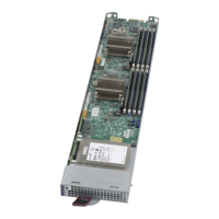
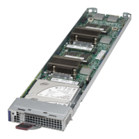
The mainboard of a MBI-6118G-T41X blade module has four (4) memory slots,
depending upon the blade model. For optimized memory bandwidth it is strongly
recommended that ALL memory slots in this MicroBlade module be populated by
DIMMs. DIMM layout is shown below in Figure 3-3.
Note: Though multiple DIMM memory module types and speeds may be supported, you
need to use DIMM memory modules of the same speed and type.
Note: For an optimized memory bandwidth, it is recommended that you populate the
memory modules in sets of four (4) DIMMs.
DIMM Installation
Caution: Exercise extreme care when installing or removing DIMM modules to prevent any
possible damage.
Installing DIMM Memory Modules
1. Power down the blade module (see "Powering Down a MicroBlade Module Unit" on
page 3-1).
2. Remove the blade from the enclosure.
3. Remove the air shroud that covers the DIMM slots.
4. Insert each DIMM vertically into its slot, starting with slots A1 and A2. Pay attention
to the notch along the bottom of the module to prevent inserting the DIMM
incorrectly (see Figure 3-4).
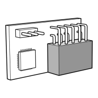
Figure 3-3. 4-slot DIMM Numbering
P1 DIMM A1
P1 DIMM A2
P1 DIMM B2
P1 DIMM B1
 Loading...