MBI-6118G-T41X MicroBlade Module User’s Manual
4-2
4-1 Control Panel
Each MicroBlade module has a similar control panel (Figure ) with power on/off button,
reset button and LEDs on the front left side of the module. The numbers mentioned in
Figure are described in Table 4-2.
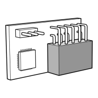
Figure 4-2. Blade Control Panel
Table 4-2. Blade Control Panel
Item Function State Description
1 Power Button N/A Turns MicroBlade module on and off
2 Power LED
Green Indicates power status “On”
Amber
Before the BMC is ready, the Amber LED will blink until the
last node out of the four is ready.
3
KVM/UID LED
(Blue)
Steady On Indicates that KVM has been initialized on this blade module
Flashing
Serves as a UID indicator (the UID function is activated with
a management program)
4
Network LED
(Green)
Flashing Green
Flashes on and off to indicate traffic (Tx and RX data) on the
LAN connection to this blade module.
Network LED
(Orange)
Flashing Orange
Flashes on and off to indicate traffic over the network (when
present in the system)
5
System Fault
LED (Red)
Steady On
This LED illuminates red when a fatal error occurs. This may
be the result of a memory error, a VGA error or any other
fatal error that prevents the operating system from booting
up.
 Loading...