EasyManua.ls Logo

Supermicro SuperServer 5019C-WR - User Manual

Supermicro SuperServer 5019C-WR
122 pages
Print Icon
To Next Page IconTo Next Page
Loading...
PB
USER’S MANUAL
Revision 1.0
SuperServer
®
5019C-WR

Table of Contents

Question and Answer IconNeed help?

Do you have a question about the Supermicro SuperServer 5019C-WR and is the answer not in the manual?

Overview

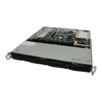
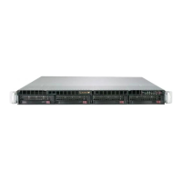
The Supermicro SuperServer 5019C-WR is a 1U rackmount system designed for professional system integrators and PC technicians. It is built around the X11SCW-F motherboard and the SC815TQC-R504WB2 chassis, supporting Intel Xeon E-2100, 8th Generation Core i3, Pentium, and Celeron series processors with up to six cores and a thermal design power (TDP) of up to 95W, utilizing an LGA1151 (H4) socket.

Important Technical Specifications:

  • Motherboard: X11SCW-F
  • Chassis: SC815TQC-R504WB2, 1U rackmount, with dimensions of 17 x 1.7 x 25.6 inches (432 x 43 x 650 mm).
  • CPU Support: Intel Xeon E-2100, 8th Generation Core i3, Pentium, and Celeron series processors (up to 95W TDP).
  • Memory: Supports up to 128GB of unbuffered (UDIMM) DDR4 (288-pin) ECC memory with speeds up to 2666MHz across four memory slots. For optimal performance, blue slots should be populated first, and DDR4 memory of the same type, size, and speed should be used. Mixed DIMM speeds are supported, but all DIMMs will run at the slowest DIMM's speed.
  • Chipset: Intel C246 chipset.
  • Expansion Slots:
    • One Proprietary WIO-L slot (JSXB1A, JSXB1B, JSXB1C) for use with RSC-W-68 riser.
    • One Proprietary WIO-R slot (JSXB2) for use with RSC-R1UW-E8R riser.
    • One M.2 slot for PCI-E 3.0 x4 (supports M-Key 2260/2280/22110 FF and Intel Optane memory).
    • One M.2 slot for PCI-E 3.0 x4 or SATA 3.0 (supports M-Key 2260/2280/22110 FF and Intel Optane memory).
  • Hard Drives: Four 3.5" hot-swap hard drive bays.
  • Power: Redundant 500W power supply (two power supply modules, PWS-504P-1R). AC input voltages range from 100-240 VAC, with a rated input current of 6.2A to 2.6A and frequency of 50-60 Hz. Rated output voltages are +3.3V (12A), +5V (25A), +12V (42A), -12V (0.6A), +5Vsb (3A).
  • System Cooling: Five 4-cm counter-rotating PWM fans are pre-installed, with one additional open slot for an optional fan.
  • Operating Environment: Operating temperature: 5° to 35° C (41° to 95° F). Non-operating temperature: -40° to 60° C (-40° to 140° F). Operating relative humidity: 8% to 90% (non-condensing). Non-operating relative humidity: 5% to 95% (non-condensing).
  • BIOS: 256 Mb AMI® Flash.
  • SATA Controller: On-chip (C246) controller supporting RAID 0, 1, 5, and 10. Supermicro SuperDOMs are supported on yellow SATADOM connectors with built-in power pins.
  • Ports:
    • Rear I/O: COM1 Port, Dedicated IPMI LAN, USB1, USB0, USB7 (USB 3.1 Gen 2), USB6 (USB 3.1 Gen 2), LAN1, LAN2, VGA Port, UID Switch.
    • Front Accessible: USB 2.0 headers (USB2/3, USB4/5), USB 3.1 Gen 2 header (USB9/10).
    • Internal: USB 3.1 Gen 1 Type-A header (USB8).
  • LED Indicators:
    • Front Panel: UID Button (illuminates front and rear LEDs for system location), Information LED (red for overheat/fan failure, blue for UID activation), NIC2 LED (LAN port 2 activity), NIC1 LED (LAN port 1 activity), HDD LED (hard drive activity), Power LED (system power status), Reset Button, Power Button.
    • Motherboard: Unit Identifier (UID) LED (LE1, solid blue for unit identified), Power Ready LED (LE6, solid green for normal VRMs, solid amber for standby, solid red for failed VRMs), Embedded Controller (EC) Heartbeat LED (LEDEC1, blinking green for normal EC), EC Thermal Event LED (LEDEC2, solid red for CPU/DIMM overheat), BMC Heartbeat LED (LEDM1, blinking green for normal BMC), Onboard Power LED (LEDPWR, solid green for system on, off for system off).
    • Hard Drive Carrier: Activity LED (blue, solid for SAS drive installed, blinking for I/O activity), Status LED (red, solid for failed drive, blinking at 1Hz for rebuild, blinking with two blinks and one stop at 1Hz for hot spare, on for five seconds then off for power on, blinking at 4Hz for identify drive).
    • LAN Ports: Green LED for activity, Link LED (green for 100 Mbps, amber for 1 Gbps, off for no connection/10 Mbps).
    • IPMI LAN: Amber LED for activity (right), Green LED for speed (left, solid green for 100 Mbps, solid amber for 1Gbps).

Usage Features:

  • Rack Installation: The system can be installed into a standard rack using pre-attached inner rails and user-installed outer rails with locking tabs. For Telco (open) racks, L-shaped brackets are used to secure the chassis. Always install the heaviest components at the bottom of the rack first and ensure the rack is stable before servicing.
  • Power Management: The system features redundant 500W hot-plug power supplies that are auto-switching capable. An amber light indicates power is off, while a green light indicates operation. In case of a power supply failure, the system can continue running on the remaining supply.
  • BIOS Setup Utility: The AMIBIOS™ Setup utility allows configuration of system settings. Access is typically via the key during boot-up. Settings include system date/time, CPU configuration (Flex Ratio, Prefetchers, Virtualization, Hyper-Threading, BIST, AES, SpeedStep, Speed Shift, Turbo Mode, C-States), Chipset configuration (Memory Frequency, ECC Support, Max TOLUD, Memory Scrambler, DMI/OPI, PEG Port, M.2 support), Super IO configuration (Serial Ports, Console Redirection), SATA and RSTe configuration (SATA Controller mode, Hot Plug, Spin Up Device), PCH-FW configuration, ACPI settings (WHEA, HPET, Native PCIE), USB configuration (Legacy USB Support, XHCI Hand-off, Mass Storage Driver Support), PCIe/PCI/PnP configuration (Option ROM execution, SR-IOV, VGA Priority, NVMe Firmware Source, Onboard LAN Option ROM), iSCSI configuration, Trusted Computing (TPM support, Secure Boot), HTTP Boot configuration, Event Logs, and IPMI settings.
  • Software Installation: After hardware installation, users should install the Operating System (OS), configure RAID settings (if applicable), and install drivers and utilities available on the Supermicro website. SuperDoctor 5 is provided for system health monitoring, including CPU temperature, voltages, power consumption, and fan speed, with alert capabilities via email or SNMP. IPMI (Intelligent Platform Management Interface) provides remote access, monitoring, and management.

Maintenance Features:

  • Accessing the System: The 5019C-WR has a removable top cover for easy access to internal components. To remove, pull the unit out until it locks, depress the two top buttons, push the cover away, and lift.
  • Processor and Heatsink Installation: The motherboard should be installed in the chassis before the CPU and heatsink. A passive heatsink is used, and thermal grease is pre-applied. Heatsink installation involves aligning and tightening four screws diagonally.
  • Memory Installation: DIMMs are inserted into slots by pushing release tabs outwards, aligning the module key and notches, and pressing down until it snaps into place, then securing with release tabs.
  • PCI Expansion Card Installation: The system includes pre-installed riser cards (RSC-R1UW-E8R and RSC-W-68). Add-on cards are inserted into the riser cards after removing the chassis cover and PCI slot shield.
  • Motherboard Battery Replacement: The lithium battery (CR2032) powers non-volatile memory. To replace, remove power, push aside the clamp, lift the old battery, and insert a new one with the positive (+) side up.
  • Hard Drive Management: Hot-swap hard drives are installed in carriers. To remove, push the release button, swing the handle out, and pull the carrier. To install a new drive, secure it to the carrier with the PCB side down, then push the carrier into the bay until it clicks. All drive carriers must remain in bays for proper airflow.
  • DVD-ROM Drive Installation: A slim DVD drive can be installed. Access involves unplugging cables, locating the locking tab, pulling it away, and pushing the drive out. Installation is the reverse process.
  • Fan Replacement: The system has five pre-installed fans, with one additional slot. Fans are not hot-plug. If a fan fails, the remaining fans ramp up to full speed. To replace, identify the failed fan, turn off power, disconnect wiring, and lift the fan. Install a new fan, ensuring arrows indicate the correct air direction, reconnect wiring, and verify operation before replacing the cover.
  • Power Supply Replacement: Redundant power supplies allow replacement without system shutdown. To replace, unplug the AC cord from the failed module, push the release tab, pull the supply out, then push the new module in until it clicks. Reconnect the power cord and verify the green LED is lit.

Safety Precautions:

  • Always use a grounded wrist strap and handle PCBs by their edges to prevent ESD damage.
  • Ensure leveling jacks are extended and stabilizers are attached to the rack for stability.
  • Install heaviest server components at the bottom of the rack first.
  • Use a regulating uninterruptible power supply (UPS).
  • Allow drives and power supply modules to cool before touching.
  • Keep the rack front door and server covers closed to maintain proper cooling.
  • Do not pick up the server by the front handles, as they are for pulling the system from the rack only.
  • Do not operate the server without the cover in place for extended periods to ensure proper airflow and prevent overheating.
  • Exercise caution around the hard drive backplane; avoid touching with metal objects and ensure ribbon cables do not obstruct airflow.
  • Only trained and qualified personnel should install, replace, or service the equipment.
  • The system must be disconnected from all power sources before accessing the chassis interior for component installation or removal.
  • Hazardous voltage or energy is present on the backplane when the system is operating; use caution when servicing.
  • Installation must comply with local and national electrical codes.
  • Improper battery replacement poses an explosion risk; replace only with the same or equivalent type and dispose of used batteries according to manufacturer instructions.
  • Fans might still be turning when removed; keep fingers and tools away from openings.
  • When installing the product, use only provided or designated connection cables, power cables, and AC adapters to prevent malfunction or fire.

Supermicro SuperServer 5019C-WR Specifications

General IconGeneral
BrandSupermicro
ModelSuperServer 5019C-WR
CategoryServer
LanguageEnglish

Related product manuals