Do you have a question about the Supermicro SUPERSERVER 5018D-FN8T and is the answer not in the manual?
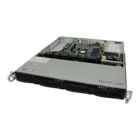
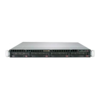
Introduces the SuperServer 5018D-FN8T, its chassis, motherboard, and key components.
Details the main features of the X10SDV-TP8F motherboard, including processor, memory, and I/O.
Outlines the main features of the SC505-203B chassis, including power, drives, control panel, and cooling.
Provides contact information for Supermicro headquarters, Europe, and Asia-Pacific regions.
Details preparations for rack installation, including choosing a suitable setup location.
Covers rack and server precautions, emphasizing stability and safe handling during installation.
Discusses ambient temperature, airflow, mechanical loading, circuit overloading, and grounding.
Provides step-by-step instructions for physically installing the server chassis into a rack.
Introduces the server's control panel, including power buttons and status monitoring lights.
Describes the function of the power and reset buttons on the control panel.
Explains the meaning of various LEDs on the control panel, indicating system status.
Details potential responses and troubleshooting steps if the server overheats.
Introduces industry-standard warnings for potential bodily injury situations.
Explains the meaning and significance of the general warning symbol used in the manual.
Provides essential instructions to read before connecting the system to a power source.
Details requirements for building's short-circuit protection device (250V, 20A).
Warns to disconnect all power sources before accessing the chassis interior.
States that only trained and qualified personnel should install, replace, or service the equipment.
Notes that the unit is intended for restricted access areas, requiring special tools for entry.
Warns about potential battery explosion risk and proper replacement/disposal procedures.
Advises that all power connections must be removed to de-energize units with multiple power supplies.
Warns of hazardous voltage/energy on the backplane during operation and advises caution.
States that equipment installation must comply with local and national electrical codes.
Instructs to handle ultimate product disposal according to all national laws and regulations.
Warns fans may still be turning after removal and advises keeping objects away from openings.
Advises using provided cables/adapters to prevent malfunction or fire and prohibits unauthorized cables.
Provides precautions for handling the motherboard to prevent ESD damage and bending.
Details how to connect data, power, and control panel cables to the motherboard.
Illustrates and lists the various front panel I/O ports available on the system.
Explains memory capacity, speeds, and provides guidelines for populating DIMM slots.
Describes the M.2 connector and its capabilities for internal mounting devices and SSDs.
Provides a detailed layout of the motherboard, identifying connectors, jumpers, and LEDs.
Details the pin definitions for power connectors: ATX, 8-pin DC, and 4-pin HDD.
Describes fan headers, chassis intrusion, system management bus, and DOM power connectors.
Explains how to use jumpers and provides details on CMOS Clear functionality.
Details LAN LEDs, BMC Heartbeat LED, and Onboard Power LED states.
Describes SATA 3.0 ports, M.2 socket, and Mini PCI-E slot.
Guides users on downloading and installing system drivers and utilities from Supermicro.
Introduces SuperDoctor 5, a system monitoring program for health information and alerts.
Provides caution regarding onboard battery installation and proper disposal procedures.
Explains electrostatic discharge (ESD) and precautions for handling sensitive components.
Details the procedure to safely remove power from the system before performing setup or maintenance.
Provides step-by-step instructions on how to remove the server chassis cover.
Outlines supported configurations for installing 3.5" and 2.5" hard drives.
Guides on installing an expansion card, including the use of a riser card.
Describes how to replace system fans and maintain proper chassis airflow.
Provides tips for ensuring optimal airflow through the chassis for effective cooling.
Details the 200W power supply unit, its auto-switching capability, and replacement.
Provides step-by-step instructions for replacing the power supply module.
Introduces the AMI BIOS setup utility for the X10SDV-TP8F and basic navigation.
Explains how to enter the AMI BIOS setup utility by pressing the <Del> key during boot.
Describes the initial Main setup screen in the AMI BIOS utility, showing system information.
Covers advanced BIOS settings, including Boot Features, Power Configuration, and CPU Configuration.
Explains how to configure SMBIOS Event Log settings, including enabling/disabling and erasing.
Covers Intelligent Platform Management Interface (IPMI) settings, including BMC Firmware Revision.
Details system security configurations, including password checks and administrator passwords.
Configures boot settings, including Boot Mode Select and Fixed Boot Order Priorities.
Explains options for saving changes, discarding changes, and exiting the BIOS setup utility.
Lists BIOS POST error codes, their messages, and descriptions for troubleshooting.
Provides an overview of the Unified Extensible Firmware Interface (UEFI) and its role.
Explains the structure of UEFI BIOS image and the process of recovering a corrupted main BIOS block.
Details the procedure for recovering the main BIOS block using a USB-attached device.
Lists processor details: model, speed, TDP, cores, threads, cache, and architecture.
Specifies memory capacity, types (RDIMM/UDIMM), speeds, and DIMM sizes.
Details the motherboard model (X10SDV-TP8F) and its dimensions.
Provides chassis model (SC505-203B) and dimensions.
Lists power supply part number, rated output power, and output voltages.
Lists certifications and compliance standards like FCC, EN, CSA, and UL.
| Maximum cache | 6 MB |
|---|---|
| Processor family | Intel |
| Processor socket | BGA 1667 |
| Intel Xeon series | D-1500 |
| Motherboard chipset | - |
| Compatible processor series | Intel® Xeon® |
| Number of processors supported | 1 |
| ECC | Yes |
| Memory voltage | 1.2 V |
| Maximum UDIMM memory | 64 GB |
| Number of DIMM slots | 4 |
| Supported memory types | DDR4-SDRAM |
| Maximum internal memory | 128 GB |
| Supported RDIMM clock speeds | 1600, 1866, 2133 MHz |
| Supported DIMM module capacities | 4GB, 8GB, 16GB, 32GB |
| Hot-swap HDD bays | No |
| Storage drive sizes supported | 2.5, 3.5 \ |
| Supported storage drive interfaces | Serial ATA III |
| LAN controller | Intel I210, Intel I350-AM4 |
| Ethernet LAN data rates | 10, 100, 1000, 10000 Mbit/s |
| Ethernet interface type | 10 Gigabit Ethernet, Fast Ethernet, Gigabit Ethernet |
| USB 2.0 ports quantity | 0 |
| Ethernet LAN (RJ-45) ports | 6 |
| USB 3.2 Gen 1 (3.1 Gen 1) Type-A ports quantity | 2 |
| Trusted Platform Module (TPM) version | 1.2 |
| On-board graphics card model | Aspeed AST2400 |
| BIOS type | AMI |
| ACPI version | 5.0 |
| BIOS memory size | 16 Mbit |
| Chassis type | Rack (1U) |
| Fan diameter | 40 mm |
| Product color | Black |
| Number of fans | 1 fan(s) |
| Sustainability certificates | RoHS |
| Power supply | 200 W |
| Input current | 2.6 A |
| AC input voltage | 100 - 240 V |
| AC input frequency | 50 - 60 Hz |
| Storage temperature (T-T) | -40 - 70 °C |
| Operating temperature (T-T) | 10 - 35 °C |
| Storage relative humidity (H-H) | 5 - 95 % |
| Operating relative humidity (H-H) | 8 - 90 % |
| Harmonized System (HS) code | 84714100 |
| Depth | 249 mm |
|---|---|
| Width | 437 mm |
| Height | 43 mm |
| Weight | 3630 g |