44
Super X11SCL-F User's Manual
Headers
IPMI CODE
BAR CODE
DESIGNED IN USA
MAC CODE
MEGERAC
LICENSE
+
+
ASpeed
AST2500
Intel
C242
Intel
i210
VGA
JD1
CPU SLOT4 PCI-E 3.0 X4(IN X8)
CPU SLOT6 PCI-E 3.0 X8(IN X16)
CPU SLOT5 PCI-E 3.0 X4(IN X8)
JSTBY1
JTPM1
JPWR1
JF1
I-SATA4
I-SATA5
I-SGPIO2
I-SGPIO1
JPWR2
JPI2C1
FAN4
FAN3
FAN2
FAN1
FANA
JIPMB1
JSD1
JSD2
BT1
JL1
SP1
MH11
MH10
JUIDB1
LE1
LEDBMC
LE3
LEDPWR
JBT1
I-SATA0
I-SATA3
I-SATA2
I-SATA1
JPG1
JOH1
X11SCL-F
REV:1.01
DIMMA2
DIMMA1
DIMMB2
DIMMB1
USB10(3.0)
USB8/9(3.0)
USB4/5
USB2/3
COM1
USB0/1
IPMI_LAN
USB6/7(3.0)
LAN2
CPU
NMI
JF1
LED
PWR
X
LED
HDD
NIC
LED
UID
2
NIC
1
RST
PWR
ON
FAIL
PS
M.2 PCI-E 3.0 X4
COM2
LAN1
JPME2
JWD1
1. FAN1
2. FAN2
3. FAN3
4. FAN4
5. FANA
Fan Header
Pin Denitions
Pin# Denition
1 GND (Black)
2 +12V (Red)
3 Tachometer
4 PWM Control
Fan Headers
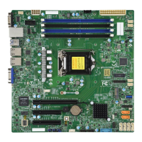
There are ve 4-pin fan headers (FAN1 ~ FAN4, FANA) on the motherboard. All these 4-pin
fan headers are backwards compatible with the traditional 3-pin fans. However, fan speed
control is available for 4-pin fans only by Thermal Management via the IPMI 2.0 interface.
Refer to the table below for pin denitions.
4
1
5 3 2
 Loading...
