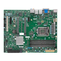
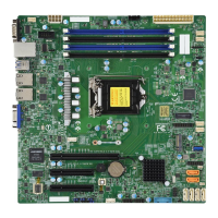
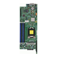
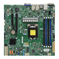
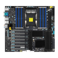
Do you have a question about the Supermicro X11SCM-LN8F and is the answer not in the manual?
Details core components like CPU, Memory, Chipset, and Expansion Slots.
Details the supported CPU types and specifications.
Details memory support, type, speed, and capacity.
Details the available expansion slots like PCI-Express and M.2.
Lists the network controllers and LAN ports.
Lists and describes various I/O devices like COM, SATA, and VGA.
Details USB ports and headers.
Details system monitoring capabilities.
Covers TPM, Watchdog, and other management features.
Covers precautions for handling static-sensitive components.
Lists safety precautions to prevent ESD damage.
Steps for installing the motherboard into the chassis.
Step-by-step guide for physically installing the motherboard.
Guides on installing the CPU and heatsink.
Detailed steps for installing the LGA 1151 processor.
Instructions for installing the CPU heatsink and fan assembly.
Instructions for removing the CPU heatsink.
Details memory support and installation procedures.
Information on supported memory types, speeds, and configurations.
Step-by-step guide for installing DIMM modules.
Step-by-step guide for removing DIMM modules.
Details the ports on the rear of the motherboard.
Details all USB ports and their pin definitions.
Describes LAN ports, speeds, and LEDs.
Details the power button connection and function.
Details the reset button connection and function.
Pinout details for the 24-pin ATX power connector.
Details the 8-pin CPU power connector pinout.
Pin definitions for the 4-pin fan headers.
Details the COM header pinout for serial communication.
Details the TPM and Port 80 header pinout.
Describes the M.2 slots and their specifications.
Details the SATA ports and RAID support.
Instructions for clearing CMOS settings.
Explains the Watchdog Timer jumper settings.
Explains LAN port LEDs for activity and link speed.
General troubleshooting steps.
Pre-power-on checks.
Troubleshooting for no power issues.
Troubleshooting for no video output.
Resolving system boot failures.
Troubleshooting memory-related errors.
Addresses loss of CMOS setup information.
Troubleshooting steps for system instability.
Instructions for removing and installing the CMOS battery.
Details various advanced BIOS configuration options.
Settings related to system boot behavior.
Enables CPU Flex Ratio programming.
Enables Intel Virtualization Technology.
Sets the number of active CPU cores.
Enables Intel Hyper-Threading Technology.
Settings related to the motherboard chipset.
Settings for memory frequency, timings, and ECC.
Sets the maximum supported memory frequency.
Enables or disables ECC memory support.
Settings for PCI Express Graphics (PEG) ports.
Settings for PCI Express.
Configuration settings for system boot order and mode.
Steps to recover BIOS using a USB device.
| Form Factor | Micro-ATX |
|---|---|
| Socket Type | LGA 1151 |
| Chipset | Intel C246 |
| Memory Slots | 4 |
| Max Memory | 128GB |
| Video Outputs | 1 x VGA |
| CPU | Intel Xeon E-2100/2200 series, 8th/9th Gen Intel Core i3/Pentium/Celeron Processors |
| Memory Type | DDR4 2666/2400/2133 ECC |
| Expansion Slots | 1 x PCI-E 3.0 x16, 1 x PCI-E 3.0 x4 (in x8 slot) |
| M.2 | 1 x M.2 |
| LAN | Dual LAN |
| RAID Support | RAID 0, 1, 5, 10 |
| IPMI | Yes |
