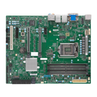
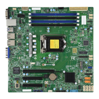
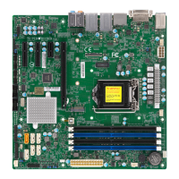
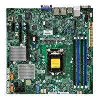
Do you have a question about the Supermicro X11SCH-F and is the answer not in the manual?
Explains the manual's purpose and target audience.
Provides an overview of the X11SCH-F/-LN4F motherboard's features and capabilities.
Explains the meaning of symbols used for warnings and notes.
Contact details for Supermicro's main office.
Contact details for Supermicro's European branch.
Contact details for Supermicro's Asia-Pacific branch.
Lists essential components included in the retail package.
Details the supported CPU and chipset for the motherboard.
Highlights unique features such as AC power loss recovery.
Explains how to monitor system voltage, temperature, and fan speeds.
Describes ACPI for power management and system event handling.
Specifies power supply connection requirements and recommendations.
Details the serial port capabilities and specifications.
Provides essential links for drivers, manuals, and support.
Essential precautions for handling ESD-sensitive components.
Step-by-step guide and tools for installing the motherboard.
Instructions for safely installing the CPU and heatsink.
Guidance on memory compatibility, population, and installation.
Identifies and describes all ports on the motherboard's rear panel.
Explains the connectors for the chassis' front panel.
Details various internal motherboard connectors.
Explains the function and configuration of motherboard jumpers.
Describes the meaning and function of onboard LEDs.
A table detailing jumpers, LEDs, and connectors for quick identification.
Details on CPU socket, core count, and TDP support.
Information on memory type, speed, and capacity supported.
Identifies the Intel C246 chipset used on the board.
Lists available PCI-Express and M.2 slots.
Details the onboard LAN controllers.
Information on the ASpeed AST2500 BMC.
Describes the onboard graphics controller.
Lists serial, SATA, and VGA ports.
Details USB port types and locations.
Outlines BIOS features and capabilities.
Explains power management features like Wake-on-LAN.
Covers voltage, temperature, and resource monitoring.
Details fan headers and speed control options.
Covers TPM, SuperDoctor 5, and intrusion detection.
Lists and explains onboard LEDs.
Provides the physical dimensions of the motherboard.
General procedures for diagnosing system issues.
Checks to perform before the system is powered on.
Steps to diagnose and resolve no-power issues.
Steps to diagnose and resolve no-video issues.
Steps to diagnose and resolve boot failures.
Steps to diagnose and resolve memory-related errors.
Troubleshooting steps for lost CMOS configuration.
Steps for troubleshooting system instability.
How to contact Supermicro for technical assistance.
Common questions and their answers regarding the motherboard.
Procedures for removing and installing the CMOS battery.
Process for returning products for warranty service.
Overview of the BIOS setup utility.
Instructions on how to enter the BIOS setup.
Details the options available in the Main BIOS screen.
Explains advanced BIOS settings.
Configuration and viewing of system event logs.
Configuration for Intelligent Platform Management Interface.
BIOS security settings, including passwords and secure boot.
Settings for system boot order and modes.
Options for saving settings and exiting the BIOS.
Lists beep codes and their meanings for POST errors.
Information on additional BIOS checkpoint codes.
Instructions for installing system drivers and utilities.
Description and usage of SuperDoctor 5 monitoring software.
Standard warnings regarding battery replacement and disposal.
Introduction to UEFI BIOS and its recovery process.
Explains the UEFI BIOS image structure and recovery.
Step-by-step guide to recover BIOS using a USB device.
| Form Factor | ATX |
|---|---|
| CPU Socket | LGA 1151 |
| Chipset | Intel C246 |
| Memory Slots | 4 |
| Maximum Memory | 128 GB |
| PCIe 3.0 x16 Slots | 1 |
| PCIe 3.0 x4 Slots | 1 |
| Supported CPUs | Intel Xeon E-2100/2200 series, 8th/9th Gen Intel Core i3/Pentium/Celeron Processors |
| Memory Type | DDR4 |
| M.2 Slots | 1 |
| SATA Ports | 6 |
| LAN | Intel I210-AT (1x 1GbE) |
| USB Ports | 2x USB 2.0 (rear) |
| Video Outputs | 1 x HDMI |
| RAID Support | Intel SATA RAID 0, 1, 5, 10 |
| IPMI | Yes |
