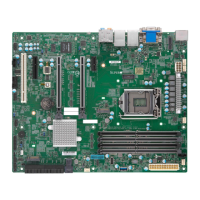
53
Chapter 2: Installation
1
+
+
X11SCW-F
REV: 1.02
DESIGNED IN USA
IPMI CODE
MAC CODE
BIOS LICENSE
BAR CODE
ASpeed
AST2500
Intel
C246
J*
J*
LE6
JIPMB1
JSTBY1
I-SGPIO1
I-SGPIO2
JF1
JPI2C1
FAN1
FAN2
FAN3
FAN4
FAN5
FAN6
JL1
JD1
JPWR1
JPWR2
BT1
JBT1
JSD2
JSD1
SRW9
SRW8
SRW2
SRW3
SRW1
SRW4
J7
SP1
JTPM1
JSXB1B
JSXB1C
JSXB1A
JSXB2
JUIDB1
I-SATA2
I-SATA3
I-SATA6
I-SATA7
I-SATA4
I-SATA5
LEDM1
LEDEC2
LEDEC1
LE1
LEDPWR
JPME2
JPG1
JPL2
JWD1
JPL1
VGA
Intel
i210
CPU
22110
2280
2260
22110
2280
2260
M.2-P_2
M.2-H_1
USB4/5
USB9/10(3.1)
DIMMB2
DIMMB1
DIMMA2
DIMMA1
X
PWR
NMI
LED
1
NIC
HDD
OH
NIC
2
FF
FAIL
PWR
RST
JF1
ON
PWR
USB8(3.0)
USB2/3
USB0/1
LAN2
LAN1
USB6/7
(3.1)
IPMI_LAN
COM2
COM1
ME Manufacturing Mode
Close pins 2-3 of jumper JPME2 to bypass SPI ash security and force the system to operate
in the manufacturing mode, which will allow the user to ash the system rmware from a
host server for system setting modications. Refer to the table below for jumper settings.
The default setting is Normal.
Manufacturing Mode
Jumper Settings
Jumper Setting Denition
Pins 1-2 Normal
Pins 2-3 Manufacturing Mode
1
1. ME Manufacturing Mode
2. VGA Enable
2
VGA Enable
Jumper JPG1 allows the user to enable the onboard VGA connector. The default setting is
pins 1-2 to enable the connection. Refer to the table below for jumper settings.
VGA Enable/Disable
Jumper Settings
Jumper Setting Denition
Pins 1-2 Enabled
Pins 2-3 Disabled

 Loading...
