MNL-2005-QRG-10b
© 2018 Supermicro Computer Inc. All rights reserved. Reproduction of this document whether in part or in whole is strictly prohibited without Super-
micro's written consent. All Trademarks are property of their respective entities. All information provided is deemed accurate at the time of printing;
however, it is not guaranteed.
注
• クイック・リファレンス・ガイドに掲載されている図は参考イラストです。ご利用のコンポーネントは、本ガイドに掲載
されている図と異なる場合があります。
• ジャンパ、コネクタ、LED表示、メモリ・サポート、CPU/マザーボードのインストール方法に関する詳細情報は、
ユーザーマニュアルの第2章をご参照ください。
前面コントロール・パネル (JF1)
CPU のインストール
ヒートシンクのインストール
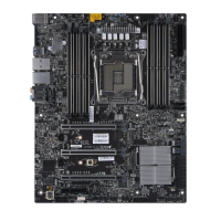
背面パネル I/O コネクタ
A. PS/2 F. USB 3.0 7 K. USB 3.0 8 P.
B. USB 2.0 0 G. 5Gb LAN 1 L. USB 3.0 9 Q.
C. USB 2.0 1 H. USB 3.1 12 M. Center/LFE R.
D. VGA I. USB 3.1 13 N.
E. USB 3.0 6 J. 1Gb LAN 2 O. S/PDIF
G
H
I
J
K
L
O
P
A
B
C
D
E
F
N
M
X11SRA
Q
R
ソケットのツメに合わせる
OPEN 1st
ネジ #3
ネジ #2
ネジ #1
ネジ #4
Power Button
1
NIC1 Activity LED
Reset Button
2
HDD LED
PWR LED
Reset
PWR
3.3 V
3.3V Stby
Ground
Ground
19 20
Power Fail LED
NIC2 Activity LED
3.3V Stby
X
X
NMI
Ground
Red+ (Blue LED Cathode)
Blue+ (OH/Fan Fail)
3.3V
3.3V Stby
 Loading...

