MNL-2005-QRG-10b
© 2018 Supermicro Computer Inc. All rights reserved. Reproduction of this document whether in part or in whole is strictly prohibited without Super-
micro's written consent. All Trademarks are property of their respective entities. All information provided is deemed accurate at the time of printing;
however, it is not guaranteed.
Notes
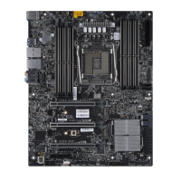
• Graphics shown in this quick reference guide are for illustration only. Your components may or
may not look exactly the same as drawings shown in this guide.
• Refer to Chapter 2 of the User Manual for detailed information on jumpers, connectors, LED
indicators, memory support and CPU/motherboard installation instructions.
참고
• 본 빠른 참조 안내서에서 사용된 그래픽은 참조용으로만 사용하십시오. 실제
구성품은 본 안내서에 표시된 도면과 똑같지 않을 수 있습니다.
• 점퍼, 커넥터, LED 표시등, 메모리 지원 및 CPU/마더보드 설치 지침에 대한
자세한 내용은 사용 설명서의 2장을 참조하십시오.
전면 제어판(JF1)
CPU 설치
방열판 설치
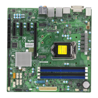
후면 패널 I/O 커넥터
A. PS/2 키보드/마우스 포트 F. USB 3.0 포트 7 K. USB 3.0 포트 8 P. 라인 입력
B. USB 2.0 포트 0 G. 5Gb LAN 포트 1 L. USB 3.0 포트 9 Q. 라인 출력
C. USB 2.0 포트 1 H. USB 3.1 포트 12 M. 중앙/LFE 출력 R. 마이크 입력
D. VGA 포트 I. USB 3.1 포트 13 N. 서라운드 출력
E. USB 3.0 포트 6 J. 1Gb LAN 포트 2 O. S/PDIF 출력
G
H
I
J
K
L
O
P
A
B
C
D
E
F
N
M
X11SRA
Q
R
소켓 키 정렬
OPEN 1st
나사 #3
나사 #2
나사 #1
나사 #4
놹낅뱱
1
NIC1 쀑ꫦ쀉 LED
뚽韥쀉튼
2
HDD LED
놹낅 LED
뚽韥쀉
놹낅
3.3 V
3.3V 鲵韥
뇆덵
뇆덵
19 20
뇊놹 LED
NIC2 쀑ꫦ쀉 LED
3.3V 鲵韥
X
X
NMI
뇆덵
ꠝ閹ꩾ+ (볁ꄵꩾ LED 넁鞮)
볁ꄵꩾ+ (OH/볡隕녚)
3.3V
3.3V 鲵韥
Power Button
1
NIC1 Activity LED
Reset Button
2
HDD LED
PWR LED
Reset
PWR
3.3 V
3.3V Stby
Ground
Ground
19 20
Power Fail LED
NIC2 Activity LED
3.3V Stby
X
X
NMI
Ground
Red+ (Blue LED Cathode)
Blue+ (OH/Fan Fail)
3.3V
3.3V Stby
 Loading...

