53
Chapter 2: Installation
LAN2
LAN1
USB0/1
USB6/7
(3.0)
VGA
SP1
Intel PCH
CPU
BIOS
LICENSE
MAC CODE
BAR CODE
IPMI CODE
IPMI_LAN
COM1
BT1
COM2
USB2/3
USB8(3.0)
J23
USB4/5
USB9/10(3.0)
JTPM1
JPWR1
JOH1
JPI2C1
LEDPWR
JD1
JPWR2
FAN1
FAN2
FAN3
FAN4
FAN5
FAN6
JF1
I-SGPIO2
I-SGPIO1
JL1
I-SATA3
I-SATA2
JSD1
JSD2
JSXB1C
JSXB1B
JSXB2
JSXB1A
JI2C1
JI2C2
JWD1
JPL2
JPG1
JPB1
JPME2
JBR1
LE1
JUIDB1
JBT1
LEDEC1
LEDBMC
JPL1
I-SATA7
I-SATA6
I-SATA4
I-SATA5
SRW2
SRW3
SRW1
SRW4
BMC
X11SSW-F
REV:1.01
Designed in the USA
JIPMB1
JSTBY1
DIMMA1
DIMMA2
DIMMB1
DIMMB2
2260
2280
22110
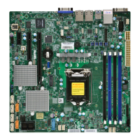
Overheat LED
Pin Denitions
Pin# Denition
1 DC 3.3V
2 OH Active
Overheat/Fan Fail LED Header
The JOH1 header is used to connect an LED indicator to provide warnings of chassis
overheating and fan failure. This LED will blink when a fan failure occurs. Refer to the tables
below for pin denitions.
Overheat LED Header
Status
State Denition
Solid Overheat
Blinking Fan Fail
M.2 Connection
The X11SSW-F board contains one M.2 NGFF socket 3 connector at J23. M.2 was formerly
Next Generation Form Factor (NGFF) and serves to replace mini PCI-E and mSATA. M.2
allows for a greater variety of card sizes, increased functionality, and spatial efciency. The
M.2 socket 3 supports both 3.0 x4 (32 Gb/s) and SATA3 (6 Gb/s) M.2 cards in 2260, 2280,
and 22110 form factors.
1. Overheat LED jumper
2. M.2
1
2

 Loading...