54
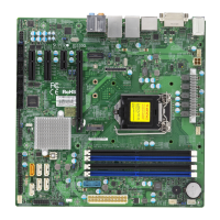
X11SSW-F User Manual
LAN2
LAN1
USB0/1
USB6/7
(3.0)
VGA
SP1
Intel PCH
CPU
BIOS
LICENSE
MAC CODE
BAR CODE
IPMI CODE
IPMI_LAN
COM1
BT1
COM2
USB2/3
USB8(3.0)
J23
USB4/5
USB9/10(3.0)
JTPM1
JPWR1
JOH1
JPI2C1
LEDPWR
JD1
JPWR2
FAN1
FAN2
FAN3
FAN4
FAN5
FAN6
JF1
I-SGPIO2
I-SGPIO1
JL1
I-SATA3
I-SATA2
JSD1
JSD2
JSXB1C
JSXB1B
JSXB2
JSXB1A
JI2C1
JI2C2
JWD1
JPL2
JPG1
JPB1
JPME2
JBR1
LE1
JUIDB1
JBT1
LEDEC1
LEDBMC
JPL1
I-SATA7
I-SATA6
I-SATA4
I-SATA5
SRW2
SRW3
SRW1
SRW4
BMC
X11SSW-F
REV:1.01
Designed in the USA
JIPMB1
JSTBY1
DIMMA1
DIMMA2
DIMMB1
DIMMB2
2260
2280
22110
SATA Ports
Six SATA 3.0 connectors are located on the X11SSW-F motherboard, supported by the Intel
C236 PCH chip. These SATA ports support RAID 0, 1, 5, and 10. SATA ports provide serial-
link signal connections, which are faster than the connections of Parallel ATA. See the tables
below for pin denitions.
Note 1: I-SATA2 and I-SATA3 are Supermicro SuperDOMs. These are yellow SATA-
DOM connectors with power pins built in and do not require separate external power
cables. These connectors are backward-compatible with non-Supermicro SATADOMs
that require an external power supply.
Note 2: For more information on the SATA HostRAID conguration, please refer to the
Intel SATA HostRAID user's guide posted on our website at http://www.supermicro.com.
1
2
1. I-SATA2
2. I-SATA3
3. I-SATA4
4. I-SATA5
5. I-SATA6
6. I-SATA7
56
4 3
SATA 3.0 Port
Pin Denitions
Pin# Signal
1 Ground
2 SATA_TXP
3 SATA_TXN
4 Ground
5 SATA_RXN
6 SATA_RXP
7 Ground
X11SSW-F SATA 3.0 Connector Types
Port # Connection Type
I-SATA 4-7
(Four)
SATA 3.0/6 Gb/s
RAID 0, 1, 5, 10
I-SATA 2-3
(Two)
SATA 3.0/6 Gb/s
RAID 0, 1, 5, 10
SuperDOM connectors
Supported by Intel C236 PCH
 Loading...

