70
Super X13DEG-OAD User's Manual
Power Button
HDD Acitivity LED
Ground
Ground
P5V_USB
I2C Clock
Fail LED_N (OH/FF/PF)
19
Ground20
1
2
Reset/UID Button
P3V3_STBY
Power Fail LED_N
Standby LED_N
Power Fail LED_P
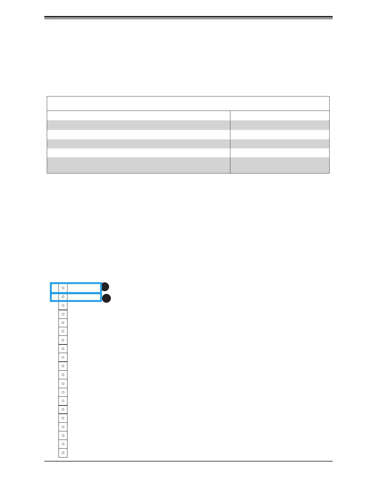
JF1
LAN-1 Activity LED (Aggregate all LAN)
I2C Data
UID LED_N
LAN-2 Activity LED
Power/RoT LED_N
P5V_USB
P5V_USB
3
4
5
6
7
8
9
10
11
12
13
14
15
16
17
18
Power On and BMC/BIOS Status LED Button
The Power On and BMC/BIOS Status LED button is located on Pin 1 of the front control panel
header located at JF1. Momentarily contacting Pin 1 of JF1 will power on/o the system or
display BMC/BIOS status. Refer to the table below for more information.
Power Button
BMC/BIOS Status LED Indicator
Status Event
Green: solid on System power on
BMC/BIOS blinking green at 4Hz BMC/BIOS checking
BIOS blinking gree at 4Hz BIOS recovery/update in progress
BMC blinking red x2 (2 blinks red) at 4Hz, 1 pause at 2Hz (on-on-o-o) BMC recovery/update in progress
BMC/BIOS blinking green at 1Hz Flash not detected or golden image
checking failure
1
2
1. Power On and BMC/BIOS Status LED Button
2. Reset Button/UID Switch Connection