74
Super X13DEG-OAD User's Manual
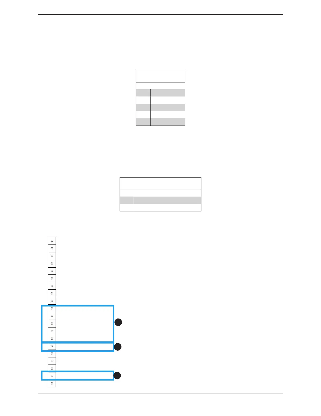
Power Fail LED Indicators
Power Failure LED Indicators are located on Pin 15 and Pin 19 of JF1. Refer to the table
below for pin denitions.
FP Power LED
Pin Denitions (JF1)
Pin# Denition
15 PWR Failure LED-Positive
19 PWR Failure LED-Negative
1. (3.3V) Standby Power
2. PWR Fail LED (Positive)
3. PWR Fail LED (Negative)
Power Button
HDD Acitivity LED
Ground
Ground
P5V_USB
I2C Clock
Fail LED_N (OH/FF/PF)
19
Ground20
1
2
Reset/UID Button
P3V3_STBY
Power Fail LED_N
Standby LED_N
Power Fail LED_P
JF1
LAN-1 Activity LED (Aggregate all LAN)
I2C Data
UID LED_N
LAN-2 Activity LED
Power/RoT LED_N
P5V_USB
P5V_USB
3
4
5
6
7
8
9
10
11
12
13
14
15
16
17
18
1
2
Standby Power
A Standby Power (I
2
C) connection is located on Pin 10 ~ Pin 14 of JF1 to provide power to
the system when it is in standby mode. Refer to the table below for Pin denitions.
3.3V Standby PWR
Pin Denitions
Pin# Denition
10 P3V3 Standby
11 Ground
12 I²C Data
13 I²C Clock
14 Ground
3