73
Chapter 2: Installation
Power Button
HDD Acitivity LED
Ground
Ground
P5V_USB
I2C Clock
Fail LED_N (OH/FF/PF)
19
Ground20
1
2
Reset/UID Button
P3V3_STBY
Power Fail LED_N
Standby LED_N
Power Fail LED_P
JF1
LAN-1 Activity LED (Aggregate all LAN)
I2C Data
UID LED_N
LAN-2 Activity LED
Power/RoT LED_N
P5V_USB
P5V_USB
3
4
5
6
7
8
9
10
11
12
13
14
15
16
17
18
1
2
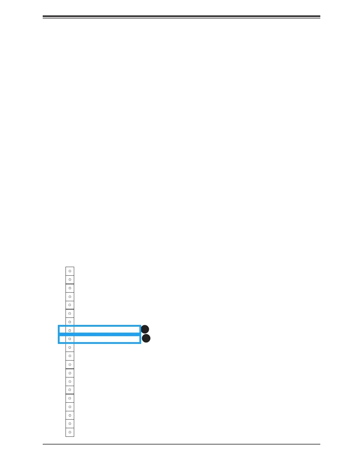
1. Standby Power LED
2. RoT Power LED
RoT (Root of Trust) Power LED
The Power LED for RoT (Root of Trust) connection is located on Pin 9 of JF1. If this LED is
on, power for the RoT chip is on.
Standby Power LED
The LED indicator for standby power is located on Pin 8 of JF1. If this LED is on, standby
power is on.