Chapter 2: Installation
2-37
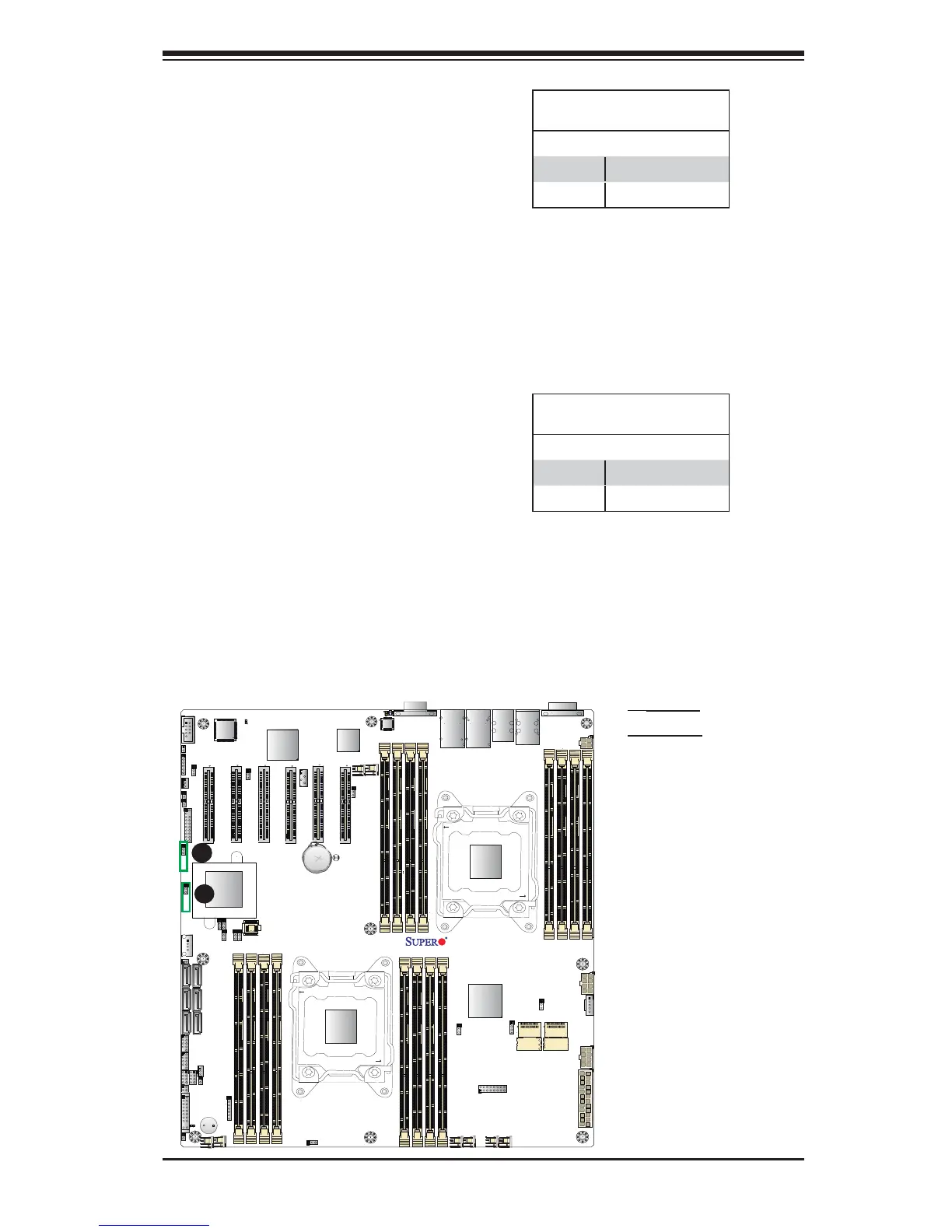
Management Engine (ME) Recovery
Use Jumper JPME1 to select ME Firm-
ware Recovery mode, which will limit
resource allocation for essential system
operation only in order to maintain nor-
mal power operation and management.
In the single operation mode, online
upgrade will be available via Recovery
mode. See the table on the right for
jumper settings.
ME Recovery
Jumper Settings
Jumper Setting Defi nition
1-2 Normal (Default)
2-3 ME Recovery
Manufacturer Mode Select
Close Pin 2 and Pin 3 of Jumper JPME2
to bypass SPI fl ash security and force
the system to operate in the Manufac-
turer mode, allowing the user to fl ash
the system fi rmware from a host server
for system setting modifi cations. See the
table on the right for jumper settings.
ME Mode Select
Jumper Settings
Jumper Setting Defi nition
1-2 Normal (Default)
2-3 Manufacture Mode
A. JPME1
B. JPME2
JPME1
JI2C1
VGA1
I-SATA1
I-SATA0
I- SATA5
I-SATA4
I- SATA3
I-SATA2
JIPMB1
JPME2
JPL1
JBR1
JWD1
JPG1
JPB1
JVRM_I2C1
JVRM_I2C2
JVR1
FAN5
FAN6
FAN8
FAN7
FAN1
FAN2
FAN3
FAN4
JF2
T-SGPIO1
T-SGPIO2
JUSB6
JSD1
JBT1
JBAT1
JTPM1
JF1
JPI2C1
JOH1
JI2C2
JL1
JSTBY1
JUIDB
J4
JD1
LED3
LEDM1
LED2
LAN2/4
LAN1/3
CPU1
CPU2
CPU2
CPU1
CPU2
CPU1
PWR I2C
UID
P2-DIMME1
P2-DIMMF2
P2-DIMMF1
P2-DIMMG2
P2-DIMMG1
P2-DIMMH2
P2-DIMMH1
P1-DIMMA2
P1-DIMMA1
P1-DIMMB2
P1-DIMMB1
P1-DIMMC1
P1-DIMMC2
P1-DIMMD1
P1-DIMMD2
USB4/5USB8/9
SLOT1 PCI-E 3.0 X8
SLOT2 PCI-E 3.0 X8
SLOT3 PCI-E 3.0 X8
SLOT4 PCI-E 3.0 X8
SLOT5 PCI-E 3.0 X8
USB6
TPM/PORT80
BUZZER
CMOS CLEAR
SLOT6 PCI-E 3.0 X8
COM2
USB2/3
COM1
USB0/1
SP1
IPMI_LAN
Battery
BIOS
JPW1
JPW2
24-Pin Main PWR
8-Pin PWR
JPW4
P2-DIMME2
JPW3
8-Pin PWR
4-Pin PWR
L-SAS4~7
L-SAS0~3
LSI SAS CTRL
Intel
PCH
JPS1
LAN
CTRL
BMC
X9DRD-7LN4F
Rev. 1.02
KB/Mouse
CPU2
CPU1
A
B

 Loading...


