Chapter 2: Installation
2-21
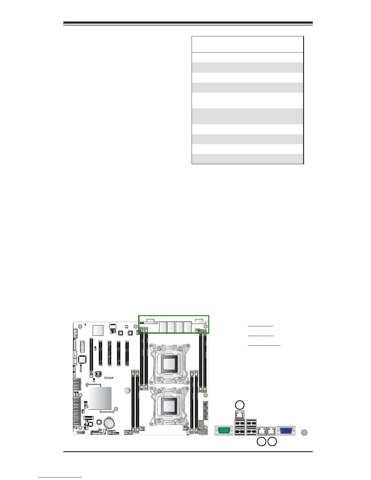
1. GLAN1
2. GLAN2
3. IPMI_LAN
Ethernet Ports
Two Gigabit Ethernet ports (LAN1,
LAN2) are located on the I/O back-
plane on the motherboard. In addition,
an IPMI_Dedicated LAN is located
above USB 6/7 ports on the backplane
to provide KVM support for IPMI 2.0.
All these ports accept RJ45 type
cables. Please refer to the LED Indica-
tor Section for LAN LED information.