2-32
X9DRL-3F/X9DRL-iF Motherboard User’s Manual
JSD1
P2-DIMMH1
P2-DIMMG1
P2-DIMMF1
P2-DIMME1
P1-DIMMD1
P1-DIMMC1
P1-DIMMB1
P1-DIMMA1
COM1
JPW4
JTPM1
LAN1LAN2
COM2
JPW1
JPW2
JPI2C1
JIPMB1
FAN3
FAN4
FAN1
FAN5
FAN2
FAN6
JPG1
JPB1
JWD1
JPME1
JWP1
JPL2
JPL1
LED2
LEDM1
JD1
JF1
6-SGPIO2
T-SGPIO1
I-SATA0
I-SATA1
SAS/SATA1
SAS/SATA2
SAS/SATA3
S-SAS4
S-SAS5
S-SAS6
S-SAS7
JL1
JI2C1
JI2C2
I-SATA2
I-SATA5
I-SATA4
I-SATA3
JBT1
JSTBY1
JRK1
UID
SLOT1 PCI-E 2.0 X1
USB0/1USB2/3
USB5
USB4
PCH
SLOT2 PCI 33MHZ
PCH SLOT3 PCI-E 2.0 X4 (IN X8)
CPU1 SLOT4 PCI-E 3.0 X8
CPU1 SLOT5 PCI-E 3.0 X8
CPU1 SLOT6 PCI-E 3.0 X8)
X9DRL-iF
Rev. 1.01
IPMI_LAN
BUZZER
KB/MOUSE
V
T
FANA
FANB
a
VGA
A
ah
USB8/9
CPU1
USB6/7
CPU2
6-SGPIO1
SAS/SATA0
Battery
JOH1
JP2
JPME2
LED1
JUIDB1
J9
JITP2
T-SGPIO2
BMC CTRL
BIOS
LAN CTRL
LAN CTRL
BMC Firmware
CPLD
Intel PCH
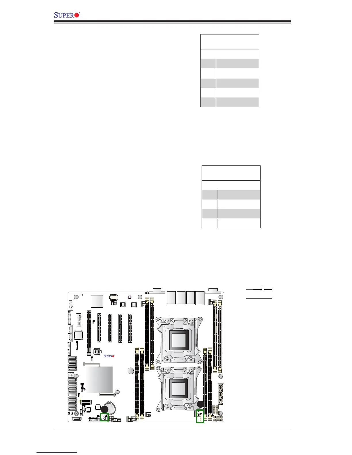
A
A. JPI
2
C1
B. JIPMB1
Power SMB (I
2
C) Connector
Power System Management Bus (I
2
C)
Connector (JPI
2
C1) monitors power
supply, fan and system temperatures.
See the table on the right for pin
denitions.
PWR SMB
PinDenitions
Pin# Denition
1 Clock
2 Data
3 PMBUS_Alert
4 Ground
5 +3.3V
IPMB
A System Management Bus header
for IPMI 2.0 is located at JIPMB1.
Connect the appropriate cable here
to use the IPMB I
2
C connection on
your system.
IPMB Header
PinDenitions
Pin# Denition
1 Data
2 Ground
3 Clock
4 No Connection
B