S101622 Rev. 1 superwinch.com | info@superwinch.com 7
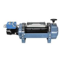
Load Control Valve A load control valve provides dynamic braking to give a controlled
smooth strop on winch-out under load.
Hydraulic Motor 1/2" SAE O-ring boss ports
Oil Suction Strainer Rating Approx. 250 microns
Return line Filter Rating 10 to 40 microns
3. HYDRAULIC SYSTEM INSTALLATION
INSTALLATION
It is vital that all hose lengths are kept to a minimum. Pressure
and flow loss is increased as hose length increases and/or bore
size decreases. Pressure and return lines in excess of 11.5 ft.
(3.5m) should be compensated with an increase in bore size.
As a general rule: All installation work on a hydraulic system
should prioritize cleanliness and accuracy to insure the hydraulic
system functions properly.
HYDRAULIC CIRCUITS