Do you have a question about the Sur-Gard SG Security Communications MLR2-DG and is the answer not in the manual?
Identifies certified equipment, outlines user responsibilities for compliance.
Emphasizes electrical ground connections for user safety.
Explains the load number for terminal devices to prevent overloading.
Covers FCC Part 15 compliance, important notes, and telephone company notification.
Addresses incidence of harm, equipment changes, and general connection notes.
Details new functionalities introduced in version 1.81, including new formats.
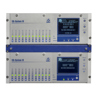
Describes the MLR2-DG, CPM2, and DRL2A as key system components.
Covers power requirements, supervision, and software compatibility.
Details the three switched-negative outputs of the CPM2.
Lists various DTMF, SIA, SK/FSK formats supported by the DRL2A.
Describes LCD screens, plain language messages, and EUROCARD design.
Covers DVACS, 2-Way Audio, Video Downlook, and expansion capabilities.
Details event buffers, real-time clock, and supervision features.
Steps for unpacking, initial setup, and default operation.
Guidance on setting up and testing the unit on a workbench.
Describes initial power-on sequence and default operational behavior.
Provides a wiring diagram for direct testing with a control panel.
Covers receiver mounting, printer, computer, and telephone line connections.
Details grounding procedures and power supply specifications.
Specifies the maximum battery charging current.
Procedures for removing and installing CPM2 and Line Card modules.
Details maximum line card capacity and a step-by-step installation checklist.
Pinout and terminal descriptions for the DML4 module.
Pinout and terminal descriptions for the DML2A module.
Illustrates the main backplane connections for power and serial/parallel ports.
Shows how DRL2A Line Cards are connected for expansion.
Describes the receiver's capability to process signals in various formats.
Lists key features like format selection, message recording, and line monitoring.
Explains the LEDs, push buttons, and LCD display functions on the DRL2A.
Describes the status indication when the DRL2A is in standby mode.
Details messages and conditions indicated in standby mode (Line Fault, CPM2 Error).
Explains how to access and navigate the Line Card menu for basic functions.
How to view printer alarm buffers and system configuration.
Procedures for checking software version and adjusting LCD contrast.
Guide to performing a cold boot and changing the line card number.
Explains messages for faulty data reception and calls, including Caller ID.
How to cancel data reception and hang up the line.
Details the connections for 2-Way audio using handset terminals.
Describes alarm type code and reserved account code methods for activating 2-Way Audio.
Explains how audio mode is indicated on the display and how it can be cancelled.
Steps for removing the DRL2A and accessing its internal components.
Details replacing EPROMs, reassembling, and initial cold boot.
Explains the cold boot process and setting the line card number.
Details turning off the program enable switch and re-installing the module.
Confirms the unit is ready for operation after upgrade and default configuration.
Format and syntax for entering commands on the CPM2 keypad.
Procedure to check programmed system configuration.
Command for changing various operating parameters and features.
Configuring event codes and libraries for 3/1, 4/1, 4/2, and 4/3 formats.
Selecting common event codes for automation software compatibility.
Enabling SIA Protocol 1 or Protocol 2 for SIA communication.
Configuring communication select, printer, receiver number, and line card number.
Settings for enabling and sending Caller ID to computer/printer.
Enabling telephone line testing and fault reporting.
Configuring programmable output, filter, buzzer, hook flash, and FBI RS232.
Settings for handshake selection, duration, and interval delays.
Configuring activation time and account codes for 2-Way Audio.
Configuring account/alarm codes for 2-Way Audio and audio event codes.
Enabling video downlook and configuring 3-2, 4/1 extended, and 4/2 extended formats.
Configuring SK FSK RS232, 4/1 Express, and SESCOA Super Speed formats.
Settings for inter-digit time, group arming, user code conversion, and equivalent line.
Configuring Modem II, Acron RS-232, and Ademco High Speed protocols.
Settings for PGM input, 3/1 extended format, inter-burst, Radionics, BFSK.
Enabling DSC SIA Audio and configuring Downlook time-out.
Commands for buffer output, line card shutdown/reactivation, and buffer management.
Details common formats (3/1, 4/1, 4/2) and Sur-Gard DTMF formats.
Explains Ademco Contact ID, Express, Super Fast, and Acron formats.
Event codes for Medical, Fire, Burglar, and General alarms.
Event codes for system, peripheral, sounder/relay, and communication troubles.
Event codes for open/close, remote access, bypasses, and tests.
Describes the CPM2 as the central processing module monitoring DRL2A cards.
Lists key features like multi-tasking, fast internal communication, and buffer sizes.
Details the CPM2's keypad, LCD display, and indicator lights.
Explains cold boot, standby mode, and configuration mode entry.
Lists the 28 configuration options available for the CPM2.
Procedure for setting the system date and time.
Allows changing or erasing CPM2 passwords and operator initials.
Setting baud rate, data bits, and parity for COM1 port.
Selecting the communication format for the COM1 port.
Setting the wait time for an acknowledge signal from COM1.
Setting the interval for supervisory 'heartbeat' transmission to COM1.
Setting baud rate, data bits, and parity for COM2 port.
Selecting the communication format for the COM2 port.
Enabling operation compliant with UL864 requirements.
Silencing the CPM2 buzzer for alarms not forwarded to COM1.
Enabling diagnostics mode to view COM1/COM2 data transmissions.
Enabling diagnostics mode to view data between CPM2 and Line Cards.
Displaying the currently installed software version of the CPM2.
Viewing the present voltage of the 12V back-up batteries.
Procedure to reset the CPM2 program to its default settings.
Changing the receiver number for COM1/printer reporting.
Configuring SCADA data transmission for remote locations.
Explains message priority and UL requirement handling for alarms.
Details COM1/Line Card diagnostics and various status messages.
Sending computer messages to printer and operator log-on procedures.
Using system command mode and examining messages on display.
How CPM2 sends data to computers via COM1 and receives acknowledgments.
Reports internal status conditions sent from CPM2 to COM1.
How the CPM2 reports when programming modes are entered or changed.
Details Sur-Gard receiver's data byte protocol and acknowledgement requirements.
Describes the standard Sur-Gard signal format for data transmission.
Explains the heartbeat signal used to supervise receiver-computer link.
Details the SIA Protocol 1 format for SIA communication.
Details SIA Protocol 2 and compatible function code blocks on DRL2A v1.8.
Lists SIA digital compatible levels supported by DRL2A v1.8.
Describes protocols for telephone number and Ademco Contact ID.
Explains protocols for Video Downlook and SIA Video Downlook.
Details the SIA AIR Downlook Protocol.
Describes the Acron Super Fast protocol format.
Details SIA Video Block and the ITI Generic format.
Explains how reported numbers are grouped by user byte.
Details Silent Knight FSK1 and FSK2 protocol formats.
Describes the FBI RS232 protocol.
Format for clock signals transmitted between systems.
Details the new SIA CIS format for computer communication.
Lists compatible automation software packages for MLR2-DG.
Reference for F7 commands to configure line card options.
Reference for commands to dump buffer data to printer or computer.
Commands for shutting down and reactivating line cards.
Reference for commands related to managing line card buffers.
Summary of utility modes accessible from CPM2.
Quick reference for CPM2 configuration options and defaults.
Brief descriptions of key line card commands.
Solutions for no communication or bad communication with the computer.
Troubleshooting steps for faulty data reception and line faults.
Solutions for CPM2 debugging mode and handshake problems.
Details various communication formats from Ademco, Radionics, and Sescoa.
Describes SIA FSK, Silent Knight FSK1/FSK2, and Varitech formats.
Details FBI RS232, ITI, and other supported communication formats.
Chart for converting decimal numbers to hexadecimal.
Chart for converting hexadecimal numbers to binary.
Table showing ASCII characters and their corresponding hexadecimal values.
Description of the SCADA system for remote alarm communication.
Shows wiring for connecting a UPS power supply to the system.
Describes the MLRV-A's capability to receive and process video images.
Explains setup options for video output and display settings.
Instructions for installing the DLGB card into a PC.
Description of PSA software for managing video images.
Details the warranty period, coverage, and limitations.
Lists damages and conditions not covered by the warranty.
Advises regular testing of the entire system for expected performance.