Do you have a question about the Sure Electronics TPA3110 and is the answer not in the manual?
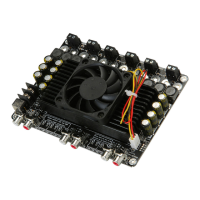
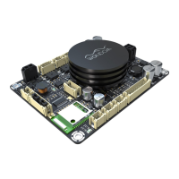
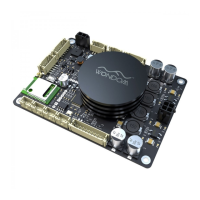
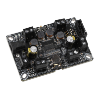
General overview of the 2x8W Class D audio amplifier board featuring the TPA3110D2 chip for dual-channel output.
Details that audio accessories are not supplied with the product; users are directed to the website for purchases.
Lists the key technical features of the amplifier board, including Class D architecture, stereo output, wide voltage range, and frequency response.
Outlines various applications for the amplifier board, such as active subwoofers, home DIY projects, and multi-channel distribution systems.
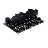
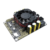
Describes the advantages of the amplifier board, such as easy installation, versatile connection options, and efficient heat dissipation.
Provides a visual guide and instructions for making the initial connection to power and speakers for the amplifier board.
Explains how to connect the power supply to the amplifier board via the onboard DC jack or terminal blocks.
Details the audio input connection options, including a 3.5mm audio jack and terminal blocks for audio signals.
Describes the terminal blocks used for connecting speakers to the amplifier board's audio output channels.
Explains the mute function, which is activated by connecting the SD pin to GND, and how to restore normal operation.
Details the single power LED indicator, marked as 'Status', which turns green upon successful power-up.
Discusses volume control, noting the absence of an onboard potentiometer and suggesting external control methods.
Presents crucial warnings for protecting the amplifier board and speaker, covering power supply, input signals, and volume adjustment.
| Chip | TPA3110 |
|---|---|
| Output Power | 15W |
| Channel Configuration | Stereo |
| Channels | 2 |
| Efficiency | 90% |
| Type | Class-D |
| Power Supply Range | 4.5V to 26V |
| Operating Temperature Range | -40 to 85°C |