EasyManua.ls Logo

Surecom SW33PLUS - User Manual

Surecom SW33PLUS
2 pages
Print Icon
To Next Page IconTo Next Page
Loading...
Key Specifications:
Test suitable antenna for walkie-talkie use
Measurement Radio RF Power output
All on LCD Power FF / Rev / S.W.R.
Specifications:
Max Power:
0.1-100W
V.S.W.R: 1.00-19.9
SWR Detection Sensitivity:
3 W min
Frequency Range:
125MHz-525MHz
5V (micro usb)
Li-ion Battery :
3.7V 500mah
In /Out Impedance :
50 Ω
Size without Socket :
25 x25 x 60 mm
(in and out ) Interface:
SMA Female
Net Weight : 160g
Package include
1x Power & SWR METER
1x English Instructions
1x USB Charger Cable
MINI VHF/UHF RF POWER & SWR METER
Features:
1 A highly visible LED meter scale on a Display makes it quick and
easy to read SWR, forward or reflected power!.
2. Maximum measurable power range up to 100W.
3. Fast check your antenna S.W.R and radio RF power watt in 3
seconds
4.Easy to install handheld Radio
Specifications:
Measurable power range: 0.1-100W
Maximum power: 100W Accuracy: mean + / - 5%
* Not for the DMR digital radio.
1.Features function (see Pic 2)
Power On : Press red button and hold 3 sec. ( All Mode)
VSWR = SWR: If not in SWR Mode, please ref to point 4
FW W (Forward): Press red button to mode " FWD Power Meter "
RW W (Power Reflected): Press red button to mode " REV Power
Meter "
Power Off : Press red button and HOLD until Display show "OFF"
2.How to measure RF Power output from transmitter (Pic.3)
Press red button - switch on all mode
Connect the "TX" to to Radio TX output .
Connect the "ANT/50 Ohm Load" to Dummy Load
!Caution : Please use correct dummy load , High power output will
damage the dummy load.
* Power Watt - Testing frequency: VHF 145.000 / UHF 430.000
3. How to Measure S.W.R. from Antenna (Pic.4)
Press red button " Power on " > "SWR "mode .Display show on:.
Connect the "TX" to RF output .
Connect the "ANT/50 Ohm Load" to ANTENNA
Test Results show 1.00 to 1.50 ,
-Mean the antenna is very good for this frequency.
Test Results show 1.50 to 9.00 ,
-Mean the antenna is not good for this frequency.
Test Results show 10.0 to 19.99 ,
-Mean the antenna is very bad for this frequency.
VHF/UHF 125-525MHz
POWER & S.W.R. Meter
Pic.2
Question and Answer IconNeed help?

Do you have a question about the Surecom SW33PLUS and is the answer not in the manual?

Summary

Product Information and Specifications

Product Features

Details key attributes like LED display, power range, and ease of use.

Device Specifications

Lists technical parameters including power, frequency, impedance, and dimensions.

Package Contents

Enlists the items included with the SWR meter.

Operation and Measurement Guide

Power and Mode Operation

Guide on powering the device on/off and switching modes using the red button.

Measuring RF Power

Step-by-step instructions for measuring forward and reflected RF power.

Measuring Antenna SWR

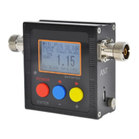
Procedure for checking the Standing Wave Ratio (SWR) of an antenna.

SWR Reading Interpretation

Explains how to interpret SWR test results for antenna performance.

Advanced Operation and Technical Details

Start-up Image Selection

Describes how to choose the start-up display mode.

Measurement Procedures Recap

Reiteration of RF Power and SWR measurement steps with diagrams.

SWR Calculation and Formulas

Explains the mathematical basis for VSWR calculation.

Important Usage Notes and Warnings

Crucial advice on correct usage, potential damage, and limitations.

Overview

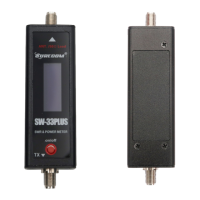
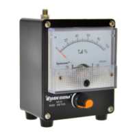
This document describes the VHF/UHF 125-525MHz Power & S.W.R. Meter, a compact device designed for testing walkie-talkie antennas and measuring RF power output.

Function Description

The device serves as a Mini VHF/UHF RF Power & SWR Meter, primarily used for:

  • Antenna Testing: Assessing the suitability and performance of walkie-talkie antennas by measuring their Standing Wave Ratio (SWR).
  • RF Power Measurement: Determining the RF power output of a radio in both forward (FWD) and reflected (REV) power modes.
  • Quick Checks: Enabling fast verification of antenna S.W.R and radio RF power watt within approximately 3 seconds.

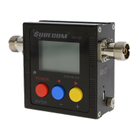
The meter features a highly visible LED meter scale on a display, making it quick and easy to read SWR, forward, or reflected power values. It supports various display modes including Power On (ALL mode), VSWR Mode, and FW Power Mode, allowing users to select the most relevant information for their testing needs.

Important Technical Specifications

The device boasts several key specifications:

  • Max Power: Capable of measuring power from 0.1W up to 100W.
  • V.S.W.R. Range: Measures SWR from 1.00 to 19.9.
  • SWR Detection Sensitivity: Requires a minimum of 3W for SWR detection.
  • Frequency Range: Operates across a wide frequency spectrum from 125MHz to 525MHz.
  • Power Input: Powered by 5V via a micro USB port.
  • Li-ion Battery: Includes a 3.7V 500mAh Li-ion battery for portable use.
  • In/Out Impedance: Standard 50 Ω impedance.
  • Size (without Socket): Compact dimensions of 25 x 25 x 60 mm.
  • Interface: Utilizes SMA Female connectors for both input and output.
  • Net Weight: Lightweight at 160g.
  • Accuracy: Provides a mean accuracy of +/- 5% for power measurements.
  • DMR Compatibility: Not suitable for DMR digital radios.

Usage Features

The meter is designed for ease of use with several operational features:

1. Power On/Off and Mode Selection:

  • Power On (All Mode): Press and hold the red button for 3 seconds.
  • Mode Switching: Short press the red button to cycle through modes:
    • FWD Power Meter: Displays forward power (e.g., "Fw: 5.52").
    • REV Power Meter: Displays reflected power (e.g., "Rw: 1.32").
    • VSWR Mode: Displays the Standing Wave Ratio (e.g., "VSWR: 2.91").
  • Power Off: Press and hold the red button until the display shows "OFF".

2. Measuring RF Power Output from Transmitter:

  • Ensure the device is powered on and in the desired power mode (FWD or REV).
  • Connect the "TX" port of the meter to the radio's TX output.
  • Connect the "ANT/50 Ohm Load" port to a dummy load.
  • Caution: Always use a correct dummy load. High power output can damage an incorrect dummy load.
  • The display will show the measured RF power in watts.

3. Measuring S.W.R. from Antenna:

  • Power on the device and select "SWR" mode.
  • Connect the "TX" port to the radio's RF output.
  • Connect the "ANT/50 Ohm Load" port to the antenna.
  • Placement: Place the antenna vertically, ensuring no obstacles are nearby.
  • Grounding: Touch the metal box of the SWR meter with your hands during measurement.
  • Press the PTT button on the walkie-talkie to initiate the measurement.
  • SWR Interpretation:
    • 1.00 to 1.50: Indicates a very good antenna for the frequency.
    • 1.50 to 9.00: Suggests the antenna is not good for the frequency.
    • 10.0 to 19.99: Implies the antenna is very bad for the frequency.

4. Start-up Image Customization:

  • Users can choose a preferred start-up image from 5 available modes.
  • After selecting a mode, long press the red button to power off until the display shows "SAVE" to store the setting.

5. Easy Installation:

  • Designed for easy integration with handheld radios.

Maintenance Features

While the manual does not explicitly detail "maintenance features" in a separate section, it provides crucial warnings and best practices that contribute to the longevity and proper functioning of the device and connected equipment:

  • Dummy Load Usage:
    • Always use a correct dummy load.
    • Avoid connecting a dummy load for extended periods as this can cause damage.
    • Ensure the watt rating of the dummy load is greater than the test RF power.
  • Antenna Connection:
    • Connecting an antenna to test power is inaccurate for power measurement.
    • Avoid connecting an inappropriate antenna for a long time to prevent damage to the walkie-talkie.
  • Power Management:
    • Shut down the device when not in use to conserve battery and prevent unnecessary wear.
  • DMR Compatibility:
    • Reiterates that the device is not for DMR digital radios, preventing potential damage or inaccurate readings if used with incompatible equipment.

These guidelines ensure the safe and effective operation of the VHF/UHF 125-525MHz Power & S.W.R. Meter, prolonging its lifespan and the integrity of connected radio equipment.

Surecom SW33PLUS Specifications

General IconGeneral
BrandSurecom
ModelSW33PLUS
CategoryMeasuring Instruments
LanguageEnglish

Related product manuals